


Sensor-based Error Proofing Specialist
Sensor-driven errorproofing can help stamping shops prevent the production of bad parts, die crashes, and downtime.
Metal formers today find that increasingly customers are no longer satisfied with just a low percentage of defective parts, measured in parts per thousand. Today customers insist on getting no bad parts at all.
Sensor-driven errorproofing can help metal stamping shops prevent the production of bad parts. In addition, it can save tens of thousands of dollars in lost production caused by crashed dies and downtime. How? Sensors detect the presence of metal—as material being fed into the press, being positioned, or ejected from the press as a stamped part or slug.
Stampers can prevent most die crashes and defective parts production if they know where the use of sensors is essential.
Ninety percent of all die protection and parts quality problems revolve around two basic functions: material progression and parts-out. To protect the die and the press, as well as to produce high-quality parts, stampers need to monitor carefully three areas:
In all automated presses, material must enter the press in a specific, measurable way.
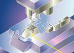
Fork Sensor. A fork through-beam laser sensor can indicate correct or incorrect guiding as it checks for buckling and progression of the feedstock. If the sensor detects incorrect guiding, it triggers the feed to stop instantly to prevent press or sheet damage (see Figure 1).
Output Sensor. Highly accurate, robust analog output inductive sensors monitor the thickness of material as it is fed into a stamping press (seeFigure 2). In roll feeds, they are set up in opposition to the sheet metal moving in between. Output parameters from the sensors correlate to the desired material thickness, and a deviation from these parameters indicates a change in material thickness or the presence of a double blank. When a sensor detects a deviation, it causes the feed to stop instantly.
While the perfect double-blank detection method has yet to be discovered, these techniques go a long way toward preventing double blanking and misfeeds.
Proximity Sensor. A hole in the part being stamped can be used to ensure that there is proper material feed, positive strip placement, and a correctly synchronized die process. An inductive proximity sensor monitors lead and trail pilot holes to verify that the guide pin is correctly engaging them (see Figure 3). Thus, it can confirm correct punch hole positioning in a progressive die as the part being stamped nears its final configuration.
Proximity Sensor. To prevent expensive die damage and "fossil imprints" on finished parts, all slugs need to be successfully ejected before the next part is stamped. Inductive proximity sensors also detect the presence or absence of slugs, verifying whether they have been ejected.
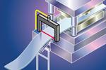
Figure 1
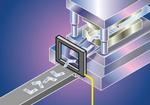
In Figure 4, a tubular inductive proximity sensor detects full punch retraction, while a self-contained through-beam fork sensor and a larger inductive proximity flatpack sensor verify successful slug ejection, or slug-out.
Self-contained, L-shaped through-beam sensors can monitor slug-out applications without interfering with the die process. L-shaped, or angle, sensors shoot a beam from corner to corner and allow for greater placement flexibility where self-contained fork through-beam sensors cannot be used. Figure 5shows an L-shaped through-beam sensor verifying the final configuration of a part after slugs have been ejected.
Optical Window Sensor. Dynamic optical window sensors provide a unique, on-the-fly verification of parts ejection from stamping dies, even when the parts eject at high speeds or at random orientations and trajectories. Stationary opaque or clear tubes or funnels can be installed within the sensor for forced directional aiming of finished parts (see Figure 6).
Photoelectric Sensor. Photoelectric sensors verify part ejection through diffuse-reflective, retro-reflective, and through-beam energized pairs in infared, visible red, or laser emissions (see Figure 7).
Bar Sensor. Bar sensors are rectangular, long-range inductive sensors that are suitable for many metallic parts-out sensing applications. Some models have adjustable sensing ranges, while others have a fixed range, giving stampers options for verifying ejection of both small and large metal formed components (seeFigure 8).
To read more about the use of sensors in stamping operations, read "Sensors clear the way for high-speed stamping: Safely navigating the press autobahn".


The Fabricator is North America's leading magazine for the metal forming and fabricating industry. The magazine delivers the news, technical articles, and case histories that enable fabricators to do their jobs more efficiently. The Fabricator has served the industry since 1970.
start your free subscription
Easily access valuable industry resources now with full access to the digital edition of The Fabricator.

Easily access valuable industry resources now with full access to the digital edition of The Welder.

Easily access valuable industry resources now with full access to the digital edition of The Tube and Pipe Journal.

Easily access valuable industry resources now with full access to the digital edition of The Fabricator en Español.
In this episode of The Fabricator Podcast, Caleb Chamberlain, co-founder and CEO of OSH Cut, discusses his company’s...


