


Contributing Writer
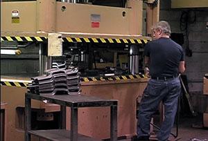 |
Does your stamping operation sometimes sound like a firing range, or do you see your presses shaking?
If so, consider the cause and effect. Shock loading is sudden force that can damage all components of a press. In extreme cases, shock can cause serious structural failure, and at the least, it can loosen components.
Shock typically is caused by the sudden release at the bottom of the stroke when punching or blanking breakthrough occurs. However, under certain conditions it also may occur at the beginning of the upstroke. Because both occur almost simultaneously, it's necessary to isolate the cause by taking a look at the dies and function involved.
The first step in locating the origin of shock may be taken at the press controls. Run the press down to complete the work, but do not allow the ram to begin to travel upward. Use the press controls to hold the ram at the bottom of the stroke. If the shock is obvious at the end of the down travel, then it is caused by the breakthrough at the bottom. If the shock isn't heard, then it's apparently occurring at the beginning of the upstroke.
Several possible factors can contribute to shock at the bottom of the stroke, including the following:
A press frame is designed with a certain amount of flexing at its rated maximum load. Manufacturers' design decisions are influenced by access to the work area, press configuration, shipping weight, and initial cost.
For example, a gap-frame press has more deflection than a straight-side press. From a user standpoint, the decision becomes how to choose the strongest frame design that will provide the required access and operate within design tonnage limits.
Preventive maintenance. Keep the system well-lubricated. All components, such as limit switches and controls, should be secure. Periodically tighten all connections and fasteners.
Oil compression. Hydraulic oil compresses approximately 1 percent for each 2,000 pounds per square inch and expands as the load is released. This usually means the press should be operated at no more than 100 percent of its rated tonnage for forming operations and 66 percent of its rated tonnage for punching.
As mentioned previously, press stamping operations are subject to shock at the point of breakthrough during punching or blanking. It occurs here because of the sudden release at the bottom of the stroke, when the press ram, the drive system, and the tooling accelerate until stopped by hydraulic oil located under the main piston.
If a press is equipped with a hydraulic counterbalance valve, you can increase the counterbalance pressure, which provides additional hold-back pressure on the oil under the main piston. This acts as a shock absorber.
In some applications, the dies are fitted with several punches in a manner that allows the press to punch all the holes at the same time. In this case, shock occurs at the point of breakthrough. This situation can be greatly improved by a process called stepping.
In its simplest form, stepping requires the punches to be different lengths, which causes some of them to engage the work before the other punches contact it. For example, if you need to punch 10 holes, instead of using 10 punches of the same length, set four punches to contact the work first and four slightly shorter punches to contact the work as the first four are at breakthrough. Two punches should be even shorter to contact the work just as the previous four are at breakthrough. This concept greatly reduces or eliminates shock.
The step is the difference in length from one group of punches to the next group. The length of this step often is overestimated. For shock reduction, it's desirable for longer punches to be at the point of breakthrough just as the next length is contacting the work. This step is not the thickness of the workpiece because, for mild steel, breakthrough occurs at about 25 percent of metal thickness. As the punch engages the workpiece and travels about 25 percent of metal thickness, the remaining thickness will fracture.
For example, 12-gauge steel has a thickness of 0.104 inch. The step between each punch length is about 0.025 in. The step required would be less for harder material and more for softer. Some trial is required for each material.
The maximum amount of stepping is limited by the overtravel possible for each individual punch and die setup. Each punch can penetrate the die by a certain distance before bottoming. The total required overtravel for a particular setup is the total of the steps, plus the overtravel of the final set of punches as the ram reaches the lower extreme of the ram travel.
With a hydraulic press, this lower stopping position is adjustable, but it should always be at least 1/16 in. below the breakthrough point of the last punches. If the stopping point is set at less than 116 in., shock will be generated by the ram beginning the uptravel during the breakthrough of the last punches.
When blanking or punching a single large hole, stepping the dies is not possible. Adding a shear to the punch or die is an alternative that can produce a similar result. This process involves grinding the bottom surface of the punch or the top surface of the die to an incline. This action provides a progressive shearing action as the press ram engages the punch into the die. The advantage is a reduction in shock and the tonnage required to complete the work. The disadvantage is that the drop-off piece is distorted by the shear incline.
Some punching or blanking operations may benefit from adding active die components, which act as shock absorbers at the bottom of the stroke. These shock absorbers can be blocks of urethane, nitrogen cylinders, or hydraulic stroke dampers.
Placing blocks of urethane to be compressed at the bottom of the stroke can be effective and inexpensive. However, this practice robs the press of some tonnage, and the blocks are not easy to adjust for proper resistance. Nitrogen cylinders built into the die system can be effective and are fully adjustable. Hydraulic stroke dampers are cylinders that are bolted into position on the bed and contacted by the ram as the press nears the bottom of the stroke. They are effective and fully adjustable for resistance.
These alternative methods of shock absorption push up on the ram as the stroke is completed. However, in most applications, this is not likely to cause a problem.
All of the previously discussed operations occur at the bottom of the stroke as the work is completed. Now consider shock as the ram begins the uptravel. Some operations end in a bottoming operation, such as when embossing, drawing, or punching dies have stop blocks at the bottom of travel. The press controls stop the ram with hydraulic oil under pressure trapped on top of the main cylinder piston.
If the ram is instantly reversed, shock can be eliminated by a decompression function. In some presses, the function is selectable and can be adjusted for duration. The time should be adjusted to the minimum necessary to allow the pressurized oil to bleed away and reduce shock. This function usually is not required for air forming or punching that does not end on stop blocks.
Air counterbalance cylinders typically are mounted on flywheel-driven mechanical presses to eliminate gear backlash, which provides operator safety in the event of broken drive components. These counterbalances also can be mounted on hydraulic presses, but they will be of little value in shock reduction.
By taking these steps to reduce shock, the life of the press and dies can be extended.
Terry Hays is president of Standard Industrial Corp., 1115 Highway 49 South, Clarksdale, MS 38614, phone 662-624-2436, fax 662-624-2581, e-mail standard@techinfo.com. Standard Industrial is a manufacturer of presses, press brakes, and shears for the machine tool industry.


The Fabricator is North America's leading magazine for the metal forming and fabricating industry. The magazine delivers the news, technical articles, and case histories that enable fabricators to do their jobs more efficiently. The Fabricator has served the industry since 1970.
start your free subscription
Easily access valuable industry resources now with full access to the digital edition of The Fabricator.

Easily access valuable industry resources now with full access to the digital edition of The Welder.

Easily access valuable industry resources now with full access to the digital edition of The Tube and Pipe Journal.

Easily access valuable industry resources now with full access to the digital edition of The Fabricator en Español.
In this episode of The Fabricator Podcast, Caleb Chamberlain, co-founder and CEO of OSH Cut, discusses his company’s...


