


Classes for the masses
Superior Tube Products provides bending course for customers, prospective customers

It’s an old story, one that has a thousand variations, one that nearly every manufacturer encounters from time to time. A design engineer has come up with a great new product, but regrettably, it has a component that can’t be manufactured. The part is too complex, or it has features that will interfere with the machine that is supposed to form it, or it will be trapped in the die after it is complete, or any one of a dozen other reasons. A related problem is a part that can’t be manufactured economically. It can be done, but it would take too long or cost too much.
These problems aren’t very expensive. The only cost is the time the engineer spent dreaming up the product and developing the individual components. With a little luck, a slight change to the design will get the project back on track.
A much bigger and much more expensive problem is a product that made it to the manufacturing stage, but contains parts that haven’t been optimized for manufacturing: a part specified as laser-cut when a simple saw cut would work just as well; an edge specified as chamfered when deburring would do; a custom-made tubular component, bent to 85 degrees, when a design change would accommodate an off-the-shelf 90-degree elbow; or a tube specified to have no ovality, requiring a mandrel, when ovality really isn’t a concern.
In all of these cases, the solution is the same: education. If the design engineers and the manufacturing engineers have the same employer, it’s a matter of arranging a guided tour of the factory floor and explaining each machine’s application, capabilities, and limitations in-depth. If it’s a fabricator or a contract manufacturer working with an OEM, it can be more difficult. If it’s a tubular product and the OEM doesn’t have much experience with tube—the jargon, the characteristics, the machines, the tooling—it can be more difficult still.
Of course, difficult doesn’t mean impossible. Fabricator and contract manufacturer Superior Tube Products Inc., Davenport, Iowa, recently decided to address this problem head-on by offering a bending course. Intended to help design engineers and purchasing agents understand how a complicated design or an over-reaching specification can have a big impact on a part’s cost, the course takes its students step-by-step through the jargon, specifications, and processes relevant to bending tubular components.
Class Is in Session
A mechanical engineer straight out of college knows a lot of information about a lot of topics, but nobody would expect him to know everything about everything, and that includes manufacturing. The education is a foundation in principles such as mechanics, kinematics, thermodynamics, materials science, and electricity, which is excellent preparation for many careers, but it doesn’t provide the fine level of detail necessary for any particular career. This is where Superior Tube Products Institute comes in. The curriculum takes design engineers and purchasing agents through tube bender anatomy, bending terminology, prints, and tooling. A few lessons from the class...
Bending Machines. At a very basic level, any forming machine is a toolholder. A rotary draw tube bender is a toolholder and a tube feeder, providing both forward motion and rotation for the feedstock. It also provides additional pressure for difficult bending applications; that is, as the tooling head rotates to pull the tube forward, the carriage applies pressure (also known as boost) to push the tube forward.
Superior also shows how simpler bending processes work, such as press bending and compression bending. Neither uses a feeding process or boost pressure, and press bending doesn’t have rotation capability.
Tooling. Tooling for press benders and compression benders is straightforward. The hydraulic ram of a press bender moves the bending die forward until it contacts the tube or pipe and applies pressure until the workpiece conforms to the die. It then goes just a bit further to offset the material’s springback, and that’s it. A compression bender is only slightly more complicated, using a wing die to wrap the tube around the bend die.
A draw bender is used when the applications are more challenging—tighter bending radii, compound bends, several bends with different radii, and so on. A basic tooling setup includes a bend die, which forms the radius; a clamp die, which clamps the tube to the bend die; and a pressure die, which applies pressure to the outer surface. Two additional tools for difficult bends are a wiper die, which prevents wrinkling on the inside surface, and a mandrel, which fills the tube to limit the amount of ovality.
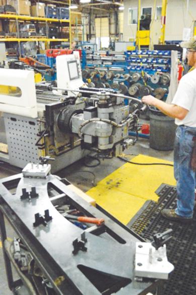
Superior Tube Products Institute provides some insights to improving the design of bent tubular components, while a tour of its facility is a crash course in dealing with the threat from low-wage countries. A typical workcell at Superior has one-piece flow and a travel distance of just a few feet. This fabrication cell includes a bender (left), check fixture (foreground), and end forming station (not shown).
Swapping out tooling to form different radii is time-consuming, so some benders can mount a set of tools (a stack). Others can accommodate tooling that performs two bending processes, such as rotary and push bending. Another option on some rotary benders is the direction in which the tooling rotates. Whether the tooling rotates to the left or right can have an impact on the length and complexity of the products it can form. The longer and more complex, the more likely the tube will collide with the machine, but it depends, in part, on the direction of tool rotation. Some benders get around this by using two sets of tools, one that rotates to the right and one that rotates to the left; the bend head rotates 180 degrees.
Material. Any office worker who has endured being put on hold for more than 30 seconds or so has learned a thing or two about materials science. Fiddling around with a paper clip for just a few seconds leads to the first lesson. It isn’t always obvious, but it applies to every bend on every paper clip: No matter how you bend it, it doesn’t stay when the pressure comes off. It always springs back a bit. Always. Tube does the same thing. Depending on the material, the springback can be so severe that it takes 189 degrees of bend to get a nice 180-degree hairpin turn.
One caveat is that the next tube might come out to 179 or 181 degrees. If it’s welded tube, it has a weld seam somewhere on its circumference, and the weld seam’s properties are different from those of the parent material. Changing the weld seam’s location from one bend to the next is a sure way to change the amount of springback from one workpiece to the next.
If the tube has all of the bends in the same plane, the best orientation for the weld seam is along the neutral axis. It shouldn’t be under compression (on the intrados, or inside of the bend) or tension (on the extrados, or the outside of the bend). If the component has bends in several planes, the weld seam should be oriented so it’s along the neutral axis of the most severe bend.
Variations from one tube order to the next also play a role in springback. The steel itself varies a bit from heat to heat; the rolling process that turns the slab of steel into sheet also plays a role, as does the forming process in the tube or pipe mill.
For particularly tricky bending applications, specifying steel’s chemistry and ordering tube or pipe from the same supplier repeatedly helps to reduce these variations. Over the long run, consistent tube is usually less expensive than low-priced tube.
Design for Manufacturability. Some bends simply can’t be made. The paper clip illustrates this principle too. Bending it in the center is easy; as you get closer to the end, it gets increasingly difficult; near the end, it’s impossible.
This is all about leverage. Bending it in the center relies on using two lever arms of maximum length, which minimizes the force necessary to overcome the material’s minimum yield strength (MYS). In other words, it can’t be any easier. Attempting to bend it closer to the end means that one of the lever arms isn’t as long. Making the same bend with less leverage requires more force. When the lever arm gets really short, perhaps 1⁄16 in., it’s impossible to grip, even with a pair of pliers.
A tube or pipe bender deals with a similar situation every time it makes a bend. The clamp die has to grip the workpiece. It uses a combination of pressure and surface area to develop enough friction to clamp the workpiece securely. If the surface area (which is the distance between bends) is too short, the bender can compensate by adding more pressure or the tooling manufacturer can make the tooling with an aggressive gripping surface, but these tactics have limits.
The other problem, a bend that is too close to the end of the tube, is easy to solve. The fabricator can simply add a little more length so the clamp die has enough surface for a good grip. After the part is bent, the end can be trimmed to the specified length.
Dimensions and Tolerances. Every bend needs a starting point, a bending radius, and a specific bend angle (or degree of bend as it’s known in metal fabrication jargon). For something like a simple 90-degree bend, it’s tempting to specify the bend location by referencing the intersection of tangent lines drawn from the straight sections, but this isn’t workable. The bender doesn’t work from intersection points and neither do the check fixtures typically used to verify the component’s dimensional integrity.
The bend’s starting point, radius, and angle can be specified in one of three ways. The simplest is based on geometric points in the Cartesian coordinate system. These are the X, Y, and Z axes of 3-D space. The other two describe the actions of the bending machine: length, rotation, and angle (LRA) or pull, turn, and bend (PTB). These are two names for the same system, which tells the bender how far forward to feed the tube, how many degrees to rotate it (if any), and how many degrees to bend it.
In addition to knowing the formats, it’s important to know how to specify various dimensions and tolerances, in terms of what’s acceptable and what’s not.
- Specifying dimensions for a straight length, a bend starting point, and the degree of bend is enough detail. Specifying the exact location of the bend’s end point is problematic in that it doesn’t allow any tolerance in the bend angle.
- By the same token, specifying the locations of two features separated by a bend can be a problem, and it gets worse as the distance between the two features increases. If the bend is off by just a fraction of a degree, one of the feature locations is going to be out of tolerance. This is akin to shooting a rifle at a distant target. A tiny adjustment in the rifle’s position can make the difference between hitting the bull’s-eye and missing the target completely.
- Specifying no ovality is tempting, but usually it’s a bad idea and, more likely than not, impossible. Unless the raw material was drawn after it was made, it already has some ovality, and bending often exaggerates the extent of it.
“It’s not uncommon for an ovality specification on a print to be half of the ovality tolerance of the raw material,” said Keith Niebur, Superior’s general manager.
Unless the tube is going into an application in which ovality is critical, such as a gauge to measure fluid flow, it’s best to consult with the fabricator on the likely amount of ovality.
- Deciding which end of the tube is most critical isn’t always easy, but often it’s necessary. This is the end that goes through the bender first.
- Finally, do the dimensions and tolerances correlate well to other parts in the assembly, downstream processes, and so on? It doesn’t make much sense to fabricate a tube that won’t work in the assembly it is intended for. (See Success Stories sidebar.)
- E-mail provides an easy way to exchange prints and related information, but OEMs should be aware that they can eliminate—not reduce, but eliminate—time, effort, and errors by providing files in a format the fabricator’s machine can understand. Why send over a CAD drawing that has to be manually converted to machine commands if an Initial Graphics Exchange Specification (IGES) file, which the machine can read, is available?
Pulling It All Together
A crash course in benders, tooling, material behavior, dimensions, and tolerances covers a lot of ground, and the time frame for Superior’s course is a single morning. Nobody would expect the designers and purchasing agents to remember all of it, so it culminates in a tool that they can use when they return to the office: a design guide. This brings together all of the important, tangible factors for quick reference: workpiece material, OD, and wall thickness; bend radius and angle; and bend criteria (the allowable amount of ovality, wall thinning, deformation, marking, and related specifications). The quantitative summary starts with a series of three formulas:
| Bending Formulas | |
| Wall factor (WF) | WF=OD/Wall Thickness |
| D of bend (D) | D = CLR/OD |
| Difficulty Factor (DF) | DF = WF/D |
It then provides a mathematical way to determine the clamp length (distance between bends):
| DF | Clamp Length |
| <18 | 2 x OD |
| 19–28 | 2.5 x OD |
| 29–56 | 3 x OD |
| 57–70 | 3.5 x OD |
The course provides one service, education, but it works to reduce a handful of challenges facing the industry these days.
“Bending has become really complex,” said Sales and Marketing Manager Lisa Wertzbaugher. “Some of the OEMs no longer want to make the continual investment in machines, tooling, and education necessary to stay current. They’re more willing to outsource it to a specialist these days.”
This is great news for tube and pipe fabricators, but it has a downside. As the bending machinery, tooling, and process knowledge at the OEM level drains away, the design engineers lose the feedback they once received from the shop floor. Superior’s course provides similar information so they can continue to be cognizant of the core principles that drive design for manufacturability.
The school also helps OEMs share challenges and solutions. An OEM involved in making agricultural equipment can learn something from one involved in construction equipment, and vice versa, if they have a chance to do so.
Finally, foreign competition is another growing trend in the modern era, and the class bears down on that too. A distant fabricator in another country might be able to provide a low-cost item, but it’s unlikely that it can provide the level of expertise necessary to help improve existing products and optimize new ones.
Success Stories
Although Superior Tube Products has held just one class so far, the company already has seen a handful of meaningful improvements in some of its customers’ products.
- “One of the prints we received had four bends,” said Keith Niebur, Superior Tube Products’ general manager. “Two of the bends had really short tangents, so we didn't have much length for the clamp die to grip the tube. We would have needed to use a machine with stacked tooling, and the part had compound bends, so it was a challenge. The tooling would have taken eight weeks to produce, and nobody has eight weeks to wait around these days.
“We knew the part was for an exhaust system, so we had a suspicion that the end points were the only points that really mattered,” he continued. “That turned out to be true, so we proposed a two-bend part that fulfilled the requirements, had long straights between the bends, and used tooling that we already had in inventory. We reduced the cost of the part by 35 percent and the lead-time to just a few days.”
- “One of our customers has an assembly that consists of two parallel tubes with a couple of bends,” Niebur said. “They’re held in place by a bracing piece, which initially was just a rectangular piece of sheet metal with two holes drilled in it, one for each tube to pass through.”
The problem wasn’t quite as bad as trying to fit a square peg in a round hole, but the effect was the same: The tubes didn’t fit. Bending imparted some ovality, and the holes were perfectly round.
Using a mandrel and attempting nearly perfect roundness was one option, but it was pricey. Ultimately the company redesigned the bracing piece so that it now consists of three overlapping pieces that are fitted to the assembly and brazed together.
- The goal of the program is to design tubular components so they are less costly to manufacture. In most cases, this means parts should be as simple as possible, but this isn’t always the way it works out. One STP customer went through the program and actually made a part more complex.
“The customer had a tube with six bends,” Niebur said. It was a lengthy part, and if it had been much longer, the bending machine itself might have been a limiting factor. A part that is too long and too complex can collide with the machine itself. However, Superior has a machine that can work around many of the longest, most complicated parts—a machine that bends in both directions.
“After the engineer saw the potential of that machine, he immediately redesigned the part so it was longer and had more bends, 10 bends instead of six,” Niebur said.
In this case, the component is used in a retrofit program. Even though this part is more expensive than the original six-bend part, it reduces the overall expense of the program because it’s a universal part—the company needs just one part, not two, for all of its retrofits.
“That never would have happened without Superior Tube Products Institute,” said Lisa Wertzbaugher, sales and marketing manager.
About the Author

About the Publication
subscribe now

The Tube and Pipe Journal became the first magazine dedicated to serving the metal tube and pipe industry in 1990. Today, it remains the only North American publication devoted to this industry, and it has become the most trusted source of information for tube and pipe professionals.
start your free subscription- Stay connected from anywhere

Easily access valuable industry resources now with full access to the digital edition of The Fabricator.

Easily access valuable industry resources now with full access to the digital edition of The Welder.

Easily access valuable industry resources now with full access to the digital edition of The Tube and Pipe Journal.

Easily access valuable industry resources now with full access to the digital edition of The Fabricator en Español.
- Podcasting

In this episode of The Fabricator Podcast, Caleb Chamberlain, co-founder and CEO of OSH Cut, discusses his company’s...
- Trending Articles
1
Team Industries names director of advanced technology and manufacturing

2
Orbital tube welding webinar to be held April 23

3
Chain hoist offers 60-ft. remote control range

4
Push-feeding saw station cuts nonferrous metals

5
Corrosion-inhibiting coating can be peeled off after use
