- FMA
- The Fabricator
- FABTECH
- Canadian Metalworking
Categories
- Additive Manufacturing
- Aluminum Welding
- Arc Welding
- Assembly and Joining
- Automation and Robotics
- Bending and Forming
- Consumables
- Cutting and Weld Prep
- Electric Vehicles
- En Español
- Finishing
- Hydroforming
- Laser Cutting
- Laser Welding
- Machining
- Manufacturing Software
- Materials Handling
- Metals/Materials
- Oxyfuel Cutting
- Plasma Cutting
- Power Tools
- Punching and Other Holemaking
- Roll Forming
- Safety
- Sawing
- Shearing
- Shop Management
- Testing and Measuring
- Tube and Pipe Fabrication
- Tube and Pipe Production
- Waterjet Cutting
Industry Directory
Webcasts
Podcasts
FAB 40
Advertise
Subscribe
Account Login
Search
Mild steel to HSS: Not just a spec change - Part I
Cutting, forming HSS requires press, die readdress
- September 25, 2009
- Article
- Bending and Forming
Editor's Note: This is Part I of a two-part article. This installment focuses on the press technology available to form and cut high-strength steel. Part II outlines cost efficiencies that stampers can realize with presses that are equipped to stamp HSS, thereby meeting cost pressures and component cost-down requirements.
Facing a shift in consumer preferences and government pressure for both fuel efficiency and increased safety standards, the automotive industry is demanding both higher-strength and lighter-weight parts. Today's pressroom is challenged to take on new high-strength steel (HSS) applications to address these challenges and also to add value to part production and assembly to meet continued pressure for cost savings.
Incorporating HSS into part applications is complex and demands more from the press system. Therefore, strategic planning and investment in the pressroom are needed. An entirely new approach that integrates part design, die design, and the press system is critical to producing a consistent-quality HSS part.
Effects of HSS on the Press
Stamping high-strength materials from 300 MPa/mm� to 700 MPa/mm�, such as dual-phase (DP) steel, transformation-induced plasticity (TRIP) steel, and complex-phase (CP) steel—or even ultra-high-strength material up to 1,700 MPa/mm� (such as martensitic steels hardened in hot forming press lines)—requires totally different approaches than stamping mild steel.
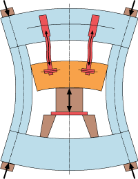
Figure 1 shows what happens to the press while cutting high-strength material. After the die closes, the increased press force generates:
- Bending of the press bed, slide, and crown
- Relief of lateral uprights
- Warping of the complete drive train with connecting rods
- Die compression
During cutting and piercing operations, the cutting die does not go completely through the material. After it cuts through about 20 percent of the total blank thickness, the material breaks through, or fractures, because HSS elongation properties are comparatively low. Figure 2 shows a typical cross section of HSS after the cutting operation.
Figure 3 shows the slide motion and press tonnage curve during cutting before bottom dead center (BDC). When the die is closed, the slide is slightly decelerated while the press tonnage increases to its maximum. After reaching maximum press force, the material is cut, and press tonnage is decreased just before the immediate drop-down that occurs when the snap-through happens. The press force becomes negative.
Depending on the material, press, and die design, this retraction force reaches up to 25 percent or more of the nominal press force. The slide rapidly accelerates down, and all energy stored within the press frame is released quickly.
Standard presses are not designed for these high negative press forces; strong impact and vibrations will damage the press in a short time. The foundation, transfer, and dies will also suffer, as will final part quality. Vibration reduces over the press cycle because of self-dampening, but will cause relative motion of the shears within the die, resulting in additional shear wear and burrs on the part.
Press Approaches to Offset HSS Challenges
While part and die design are essential to resolving many of the HSS blanking issues, press systems can be designed to help offset these challenges.
Obviously, as the material's tensile strength increases, the required press tonnage also increases. While HSS generally is thinner than other materials for a given application, changing to HSS typically results in a need for 25 percent more press tonnage (see Figure 4).
Link Drive. A link drive can reduce the impact when the upper die touches the blank holder. This reduces drawing speed to help improve part quality. Additionally, the use of bed cushions with preacceleration also can allow higher stroke rates without increasing the die impact. Vibration is prevented, and the cushion's NC algorithm provides more accuracy in controlling the preset values.
Solid Press Frame, Drive Train, Gearing. Presses for piercing and trimming HSS need to be designed with a very solid press frame for minimum deflection, a very solid drive train covering positive and negative press forces, gearing with minimum backlash (since moment occurs in two directions), and minimum force flow within the press frame and drive train.
Die Reinforcements. High acceleration of forces affects die elements in the same way that it affects the press, so the general die structure must be reinforced. Die gibbings must be robust enough to avoid lateral movements that change the trimming clearance and lead to additional wear on the overall die.
Dampening. All active parts should be designed for quick exchange and easy maintenance. Movable parts such as cams must be dampened by nitrogen cylinders or something similar. Shears need to be fixed carefully on solid basic frames (such as cast iron with higher tensile strength), while the shear itself needs to be made out of cold-work tool steel with simultaneously increased levels of wear resistance, hardness, and toughness.
Heat Treatment. To reduce wear on the die, heat treatment or special inserts are required. These inserts are hardened, plasma nitrated, or coated with CVD or PVD. The trimming angle should not increase by more than 5 to 10 degrees. This requires additional cams with dampening systems.
These approaches require larger die sizes or increased trimming operations and a flexible transfer system for part reorientation from station to station.
Early integration of the design and manufacturing processes allows different radii, varied hole sizes and positions, and part tolerances to be considered, which can prevent high production costs later.
Dampening Technology
Another approach to blanking advanced high-strength steel (AHSS) and press-hardened parts is a dampening process that softens, or reduces, the cutting impact, or break-through, to produce clean, burrless blanked surfaces and edges.
Mechanical components are mounted in a plate positioned between the slide and upper die (see Figure 5) and a software module supplements the existing press control to monitor pressures and cutting forces and optimize the cutting process.
The plate consists of nitrogen cylinders arranged in a pattern with a regular grid distance. The nitrogen cylinders are used for the blank-holding function only. Hydraulic cylinders in the same grid pattern are used for blank holding and dampening as well. All cylinders are activated by the pressure pins of the die.
With the process, frame spring energy is absorbed and buffered. Blanking energy is picked up at the origin. This reduces strong vibrations, which decreases the wear on the press components and die. Lateral wear is decreased on the cutting blades, and the dies do not need additional internal damping and blank holder equipment working in the vertical direction.
The software module monitors pressures and cutting forces, and optimizes the cutting process by controlling the storage and release of energy. Because the software is a self-adapting control, the process is very stable as process conditions change.
Energy is stored by the system and released in a controlled manner when the slide opens after BDC. Snap-through shock is prevented, and no negative forces apply to the system. The damping cylinders are located above the cutting area inside the die to eliminate the influences of slide and bed bending.
It can be retrofitted into many mechanical and hydraulic presses, but it requires a shut height sufficiently large enough to accommodate the equipment. It also needs special die design.
Servo Drives for HSS Cutting Quality
Servo drive press technology allows stampers to freely program the slide motion curve to reduce cutting speed while increasing output.
The approach, forming speed, and slide return speed can be optimized to suit the part and the automation process. This can significantly reduce total cycle time and improve part quality.
Productivity gains as high as 60 percent can be achieved with optimized programming of the slide motion curve. Implementation can take less than half a shift, involving no modifications to the process or die.
Advanced torque drives work with low RPM but provide high torque. With a two-stage drive train that does not have additional timing belts or spindle drives, the forming cycle can change torque and force loads and directions quickly.
Figure 6 shows different slide motion characteristics around BDC. The servo drive allows stampers to reduce the acceleration of the slide and die, resulting in less vibration after the impact. In some cases, it also can reduce press tonnage.
The servo press provides energy not through the big inertia mass of a flywheel, but by the main motors and transfers it directly into the process. The resistance of the die-closing forces and buildup of press tonnage reduce the rotation of the torque motors, in some cases nearly to zero, depending on the process.
The smooth servo motion works with programmed slide motion to reduce drawing and trimming speeds. The result is a lower cycle time without a reduction in part quality or the need for die modifications.
Related Companies
subscribe now

The Fabricator is North America's leading magazine for the metal forming and fabricating industry. The magazine delivers the news, technical articles, and case histories that enable fabricators to do their jobs more efficiently. The Fabricator has served the industry since 1970.
start your free subscription- Stay connected from anywhere

Easily access valuable industry resources now with full access to the digital edition of The Fabricator.

Easily access valuable industry resources now with full access to the digital edition of The Welder.

Easily access valuable industry resources now with full access to the digital edition of The Tube and Pipe Journal.
- Podcasting
- Podcast:
- The Fabricator Podcast
- Published:
- 04/09/2024
- Running Time:
- 63:55
In this podcast episode, Brian Steel, CEO of Cadrex Manufacturing, discusses the challenges of acquiring, merging, and integrating...
- Industry Events
16th Annual Safety Conference
- April 30 - May 1, 2024
- Elgin,
Pipe and Tube Conference
- May 21 - 22, 2024
- Omaha, NE
World-Class Roll Forming Workshop
- June 5 - 6, 2024
- Louisville, KY
Advanced Laser Application Workshop
- June 25 - 27, 2024
- Novi, MI


