


Sensor-based Error Proofing Specialist
In addition to detecting the weld seam, some modern electronic sensors are sophisticated enough that, when properly programmed, they can differentiate between a good weld and a bad one.
Picture the activity in a typical automotive assembly plant. Dozens of synchronous industrial processes run full-tilt. Stamping presses bang out parts; robotic welding cells bond door, hood, and body components; the paint shop runs full-bore; suppliers continuously drop off just-in-time deliveries; and every part is expected to be 100 percent perfect—no exceptions. Margins are tight, leaving no room for error.
Suddenly the line stops. An assembler can't get an exhaust system to fit, and the supervisor's blood pressure skyrockets.
If you're the supplier who provided that exhaust system, you can expect to pay a financial penalty for every minute the line is stopped. Then you can expect a visit from the automotive manufacturer, an audit, and a thorough scrutiny of your manufacturing process, not to mention the required inspection and sorting of your products (with rework for components that do not conform to specifications). After the dust settles and your already skinny profit margin has nearly disappeared, you will ask yourself two questions: What went wrong? What could I have done to prevent it?
In any manufacturing process, sooner or later a problem will crop up, and the result will be a batch of bad parts. The best we can do is to anticipate problems and try to prevent them.
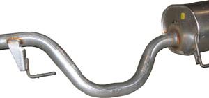
Not so long ago automotive exhaust systems were essentially disposable. They required frequent repairs and wholesale replacement. Not so today. Modern exhaust systems last for years—the result of decades of research and development and continuous improvement on the part of exhaust component suppliers.
Such manufacturers don't have to stop there. Why not go a little further and prevent dimensional variances that result in an exhaust system that doesn't fit? Off-the-shelf, cost-effective, repeatable sensing systems can address many manufacturing challenges and help prevent small problems from turning into large ones.
Mandrel Ball Detection. It doesn't happen often, but if a mandrel ball (also known as a doughnut) on a tube bending mandrel comes off and goes undetected, it can travel with the exhaust system and end up installed on a car on the assembly line. It's similar to stuffing a potato into an exhaust pipe. One effect is the same (the car won't start) and the other is different (nobody laughs).
Standard infrared, diffuse-reflective, and high-excess-gain photoelectric sensors (see Figure 1) can detect the presence of mandrel balls on the tube bending mandrel. These devices even work in environments clouded by oily mist and mandrel lube. If it's a really oily situation, air knives or blowoff shields go a long way in preventing fouling of optical lenses.
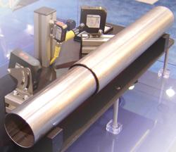
Hanger Rod Detection and Position Measurement. Hanger brackets have critical dimensions and must be welded precisely to the exhaust system so that it will fit properly to the vehicle's brackets. Assemblers have a limited time to mount the exhaust system, so the fit must be perfect. Long-range analog (0-10 V or 4-20 mA output) laser systems can confirm the presence and position of inlet and outlet hangers (seeFigure 2). Such laser systems also allow you to program high/low or go/no-go limits. Some units have two sensors, providing both measurement feedback and on/off set points.
Although many exhaust system manufacturing fixtures are fully automated, many are not, for a variety of reasons. The size or complexity of the exhaust system can prohibit completely automated welding of system components. In such systems, a clamping fixture holds exhaust system components in place and a person does the welding. Although it can be a challenge, you can integrate sensing systems to detect inlet and outlet rods and supports with conventional sensing devices provided you can implement dependable, predictable fixtures.
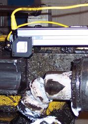
Figure 1A photoelectric sensor can determine the state of your tube bender tooling. Programmed to look for the doughnuts of a tube bending mandrel, it reports whether all of them are present. If the sensor detects that one is missing, you know where to start looking.
Laser welding stainless steel tube generates a unique color pattern that a sensor can detect. The laser pattern is so repeatable and predictable that the sensor, which can detect three shades of color and has five levels of tolerance, can sense the difference between a good weld and a bad one. The system uses three sensors that are wired in series and trained to see the same pattern. If the sensors detect any variance in the color pattern, the control system shuts down the laser welder and alerts personnel to inspect the tube.
Other conventional sensors are suitable for welding workcells. For instance, high-resolution analog inductive proximity sensors have been around a long time, but in the past their linearity was not predictable. Today's devices are much more advanced, and many have excellent linearity properties. They can profile weld seams and measure weld bead dimensions or component features. One type has three discrete set points to indicate a high/low or go/no-go condition or provide analog feedback.
Contrast photoelectric sensors can differentiate small-area contrast differences that typical sensors miss. They can help produce a tight weld seam, even with a small seam width.
So you have installed some sensors, integrated them with your control systems, gotten the workcells up and running ... and you still turn out bad parts on occasion. You looked for the root cause and determined that the sensors are failing at an alarming rate. The chief problem here is that the sensor is not a good match for the application.
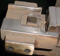
Loading Impact. Sensors in weld cells often are mounted with lightweight brackets that are not specifically designed for impacts, leaving the sensor vulnerable to parts-loading hits. Sensor damage can be prevented by using mounting systems that resist impacts and keep the sensor out of harm's way (see Figure 3).
Sensor Coatings. Nearly every sensing device is designed for a specific application and won't last long if used in an environment it was not designed for. If you install a lightweight, non-weld-resistant sensor in a weld cell, you will get predictable results: The sensor will fail prematurely, maybe within days or even hours of installation. It happens all the time.
A coating on the sensor body can prevent weld spatter accumulation, facilitate spatter removal, and provide a thermal barrier.
Sensor Connections. Sensor connection burn-through is a common problem in welding workcells. Weld spatter damages sensor connections, causing downtime and depleting the maintenance budget. A connector jacketing material such as TPE (thermoplastic elastomer) is flexible and resists heat damage.
Myriad sensors are available, and nearly every one of them was designed to solve a specific problem. It's safe to assume that your problem already has been solved; it just requires a little rock-flipping to find it.
Whether it's feature detection, weld seam detection and measurement, workcell process improvement, or errorproofing that you need, you have dozens of off-the-shelf sensors available to choose from. Understanding what they do and how they do it are the first two steps in using them to increase production, reduce downtime, improve part quality, and cut scrap.
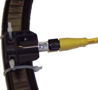
Measuring the arc-on time in a welding workcell can be a challenge. In one specific instance, the controller had no way to measure this parameter, so the fabricator experimented with a tubular-style magnetoresistive sensor. He positioned the sensor perpendicular to the master cable until he found a sweet spot, a location where the sensor detected the magnetic field reliably while welding was in progress. Although this type of sensor typically is used for determining a pneumatic cylinder's piston position to indicate clamp or unclamp, it worked well in this application.

The Tube and Pipe Journal became the first magazine dedicated to serving the metal tube and pipe industry in 1990. Today, it remains the only North American publication devoted to this industry, and it has become the most trusted source of information for tube and pipe professionals.
start your free subscription
Easily access valuable industry resources now with full access to the digital edition of The Fabricator.

Easily access valuable industry resources now with full access to the digital edition of The Welder.

Easily access valuable industry resources now with full access to the digital edition of The Tube and Pipe Journal.

Easily access valuable industry resources now with full access to the digital edition of The Fabricator en Español.
In this episode of The Fabricator Podcast, Caleb Chamberlain, co-founder and CEO of OSH Cut, discusses his company’s...


