


Vice President

As the oil and gas industry has changed over the years, the quality standards for tube and pipe have gained in importance. Drilling is taking place in more remote locations, often many miles offshore; horizontal drilling capability allows drilling at ever-greater distances; and to find new sources, drilling is going deeper than ever before. For tube and pipe producers involved in this worldwide market, accurate and reliable nondestructive testing (NDT) is a requirement.
A chain is only as strong as its weakest link, and using this adage in the energy industry means that an oil extraction operation is only as productive as its weakest component. A burst pipe equates to a productivity loss and a revenue loss, and repair costs can be extraordinary.
Working offshore entails working in water up to 10,000 feet deep. At this depth, the seawater temperature typically is 35 degrees F and the water pressure is 4,400 pounds per square inch. A failure at this depth can be severely costly, entailing a $20 million repair, and the production loss can tally $500,000 per day. The liability for a failure at this depth can put the production company’s future at risk. For products used in such conditions, it’s imperative that production, testing, and placement go smoothly.
While many NDT processes are available for the variety of tube fabrication methods used in industry, the three most common methods for tube and pipe are eddy current (EC), ultrasonic testing (UT), and magnetic flux leakage (MFL). As their names imply, they rely on electrical currents, ultrasonic waves, or magnetic flux that travel through or along the tube or pipe. A receiver or detector monitors the test signal and compares it to a reference signal, a baseline established from a defect-free length of tube or pipe, containing machined notches or artificial defects mandated by the various testing specifications. A material defect causes a change in the way the test energy flows through the tube or pipe; the receiver interprets this change as a flaw and alerts the operator, marks the defect location, or both.
The EC method is suitable for products that have wall thicknesses less than 0.200 inch. Many applications require detection of both inside-diameter (ID) and outside-diameter (OD) surface notches. This requirement mandates either MFL or UT.
EC. The basis for an EC test is electromagnetic induction. An EC system applies an alternating current (AC) stimulus, typically between 2,500 cycles per second (also known as hertz [Hz]) up to 100 kHz, to a coil that surrounds the tube or pipe under test. The AC stimulus creates an alternating magnetic field around the coil, causing an electrical current to flow through the tube or pipe. This circular current, the eddy current, opposes the primary field in the coil.
For ferromagnetic tubes the EC test coil also is energized with a strong direct current (DC) magnetic field by means of a large, separately wound electromagnet. The function of the electromagnet is to saturate the material under test magnetically. This allows much deeper excitation and removes any permeability variations that are interpreted as noise.
UT. The UT principle uses sound waves at frequencies beyond the threshold of human hearing (20 kHz), commonly in the frequency range of 2.25 to 25 MHz. Ultrasonic testing uses either a piezoelectric transducer or an electromagnetic acoustic transducer. The former generates the sound wave outside of the object under test and needs a couplant to transfer that energy to the object under test; the latter generates sound waves within the object under test and needs no couplant.
MFL. MFL relies on a DC power source to create a magnetizing field that generates an intense magnetic flux in the test material. Internal or surface defects cause some of the magnetic flux to leak beyond the material’s surface, where it can be detected by a flux-sensing probe. The amplitude and frequency of the voltage generated by the flux sensor corresponds to the severity and location of the discontinuity.
MFL can be a very powerful and economic method to test large-diameter, heavy-wall pipe and tube, satisfying many American Petroleum Institute (API) testing requirements. This method can be quick and dirty in that it doesn’t need a couplant.
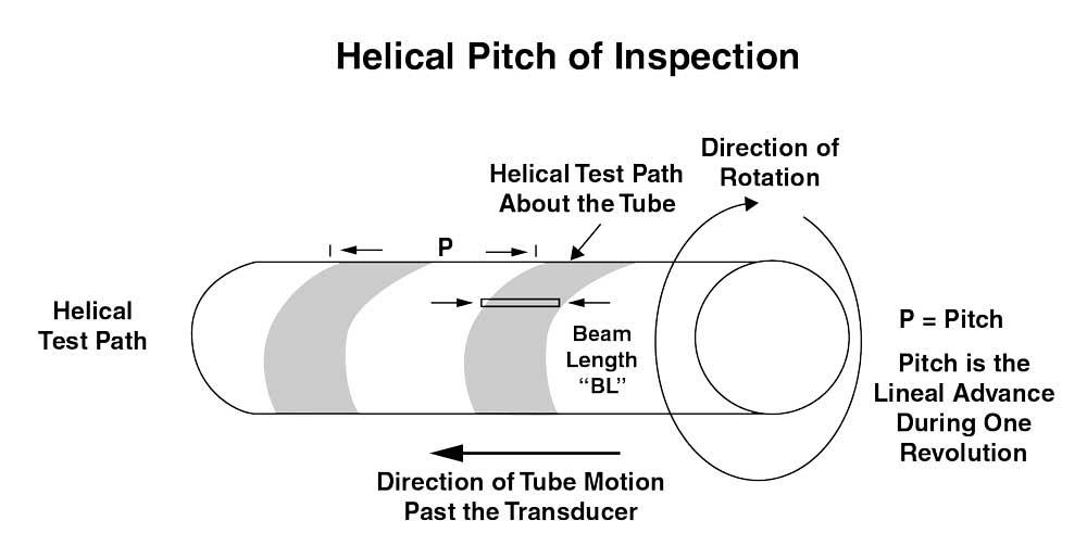
Figure 1
As the tube moves along the test apparatus, transducers revolve around it. The linear advance of the tube and the revolutions of the transducers combine to create a helical pattern. This illustration shows a single transducer, but an actual test setup uses several transducers for full coverage.
Testing setups come in two varieties: online and offline.
Online. Online testing takes place as the tube or pipe is manufactured on the mill. It’s a continuous test, running without interruption. It has an advantage in efficiency in that it doesn’t add any steps to the manufacturing process. A disadvantage is that it’s a one-and-done arrangement. If the operator questions the result and wants to verify that the system has indeed signaled a flaw and not generated a false positive, he can’t back up the process and test that portion of tube again. While online testing is a powerful tool, it can’t be the only tool for oil and gas products. Because the API mandates that NDT must be done after final processing, an offline test must be the final NDT process.
Offline. Offline testing takes place after the tube or pipe has been formed, welded, cooled, straightened, annealed, cut to standard lengths, and gone through other subsequent processes steps, such as hydrostatic pressure testing.
Offline tests are discrete tests, checking one length at a time. They require a secondary handling, which adds time and additional material handling and requires more floor space, but the advantages are versatility, repeatable testing, and a higher inspection level. Many arrangements are available, and the operator can test an item more than once if necessary to verify a flaw’s presence, size, or location. Alarm indications can be proven (false positives can be ruled out), and in some cases surface flaws can be eliminated.
UT processes require a coupling medium between the transducer and the material under test. The medium usually is water or a gel. Processes include contact, immersion, bubbler, and rotary.
Contact. An ultrasonic contact test is almost always an offline setup in which the transducer is coupled to the object under test and the couplant is a high-viscosity fluid. Contact testing normally is a manual operation.
Immersion. Immersion testing is an offline setup in which the transducer and the test object are immersed in water. When the transducer is set so it is perpendicular to the item under test, the sound beam creates longitudinal waves in the tube or pipe and can be used to detect laminations. The same transducer can be used to measure the wall thickness. When the transducer is set at an angle to the item under test, the sound beam likely creates shear waves, which can be used to detect defects on the OD, on the ID, or below the surface.
Bubbler. A bubbler system uses a column of flowing water inside a curved shoe and can be online or offline. The sound beam is projected through the water perpendicular to the test surface to produce longitudinal waves. It also can be set to an angle to the surface to produce shear waves.
An alternative is an irrigated shoe in which the sound path is inside a plastic wedge and only a very thin water-coupling layer is necessary.
Rotary. A rotary system is an apparatus in which the transducers revolve around the tube or pipe as it moves past them. Although most rotary setups are offline, on some occasions a mill can accommodate a rotary system.
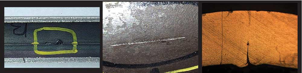
Figure 2
Three flaw examples on an umbilical line are a small pinhole detected by EC, but difficult to find with UT (left); a seam defect detected by EC and UT; and a weld defect on the ID found by UT but not by EC. These results demonstrate the power of using two systems.
Transducers are strategically positioned inside the rotary unit to allow full volumetric coverage of the product to be tested. The rotation speed and product feed speed are coordinated to achieve 100 percent coverage. This is done by use of a scan plan and by documented dynamic proof of detection of required notches at the actual test speed to achieve the mandated inspection level (see Figure 1).
A key point in setting up a comprehensive testing regimen is understanding the various types of flaws and where flaws occur. Another is compliance with API testing requirements, which stipulate that the system capabilities have been evaluated and documented, including coverage calculation, wall thickness measurement, and defect detection. The documentation also must include specific information about transducer orientation, threshold settings, and test result repeatability.
Defects that run along the length of the tube are longitudinal; those that run across the width are transverse. Many defect types are neither primarily longitudinal nor transverse. To simulate manufacturing defects, API stipulates that the tube or pipe producer must make a length of reference pipe by making notches and drilling holes of specific sizes in a sample that has no known defects. The manufacturer uses these to calibrate the NDT system.
Some flaws are exclusively or preferentially detected by one method or another, so a comprehensive testing program uses several NDT methods. A combination of UT and EC is appropriate for small-diameter, medium-wall applications, specifically umbilical lines. UT and MFL make a suitable combination for large-diameter, heavy-wall applications such as drill pipe, line pipe, and casing.
A Setup for Umbilical Lines. Key offshore components are umbilical lines, which are tubulars that run from an offshore oil platform to a well or a cluster of wells. Used for hydraulic lines, chemical injection lines, and sheaths to protect electrical cables, umbilicals connect an offshore oil platform to a subsea manifold system, which is a central oil-collection point for a cluster of wells.
Umbilicals are extremely long and usually are tested inline by using an EC encircling coil. This normally is installed in a position after inline bright annealing.
Note that a full body inspection of an umbilical line can require some additional equipment. A typical umbilical material is lean duplex 19D, which is 50 percent austenite and 50 percent ferrite. This grain structure tends to shield or repel the eddy current field. For eddy current to penetrate the metal surface, it is necessary to saturate the tube wall with a magnetic field. To do this, the setup requires an electromagnet and a power source that can generate sufficient magnetic field strength.
A secondary test is an offline UT rotary system with three transducers, one each for clockwise shear, counterclockwise shear, and wall thickness. A water column maintains coupling between the transducers and the tubing as the transducers orbit the tube.
A final test is air under water (a common leak test).This three-part test can find pinholes (penetrators), strip defects, and weld defects (see Figure 2).
A Setup for OCTG. API specifies the dimensions, material grades, mechanical properties, and other requirements concerning steel products used as casing or tubing for wells in API 5CT. It also establishes the notch dimensions for the various grades and quality levels, the NDT method, and data collection requirements.
An ultrasonic rotary setup is suitable for verifying the wall thickness, but some grades require only 25 percent coverage. According to API 5CT, section 10.13.4, pipes specified to PSL-2 and PSL-3 require 25 percent and 100 percent wall thickness coverage, respectively. However, some customers have their own wall thickness requirements.
To achieve full-volume testing, a setup usually needs at least seven testing directions: one for the thickness and lamination defects, two for longitudinal notches (clockwise and counterclockwise), two for transverse notches (forward and reverse), and two for oblique notches (clockwise and counterclockwise). The number of transducers also is related to the production speed—more transducers are needed for faster line speeds.
Test references include 6-mm, flat-bottomed drilled holes and pipe with a wall thickness coupon set to the minimum allowable wall thickness.
One drawback is that some conventional NDT methods have limitations in their abilities to test to the very end of the product. These untested ends must be cut off and discarded, resulting in a substantial loss of product and revenue. Furthermore, some users require a higher level of inspection because the end is to be flared, threaded, or welded in the field.
An unconventional end inspection process uses a large number of transducers in a small area. Under common testing circumstances, crowding the transducers causes interference. However, because this system uses a tube rotation rate that is relatively slow—3 to 5 revolutions per second—the pulse repetition rate can be standardized at 1 kHz, and all transducers can be pulsed relative to this rate. Any transducer-to-transducer interference can be eliminated by the standard transmitter delay function that is built into the pulser/receiver unit.
The tube is transferred to the test system by a walking beam transfer device. As the tube moves into position, a mandrel at the tube end engages the tube and seals it. The transducer carrier moves into position at the bottom of the tube; an air spring applies pressure to hold the transducer unit in the correct position. Adaptive pitch rollers keep the transducers a constant distance from the tube or pipe wall.
Rather than relying on the operator to make changes in the setup when changing to a new pipe or tube diameter, this method relies on a diameter gauge to adjust the tube follower roll set to keep the distance from the transducer to tube surface constant. This keeps the sound entry point constant (bottom dead center), which keeps all angles and the sound path constant. This nearly eliminates the need to make adjustments to the transducers, minimizing changeover time. Also, the operator doesn’t have to figure the rotation rate. The operator enters the OD at the control panel; an encoder determines the rotation rate.
Notches are made on a test standard that is the same diameter and wall thickness as the tube to be tested. All notches and drilled holes and the thickness coupon are made according to the same requirements as the full body test requirement.
The length of the tested tube end is approximately 10 in. The testing time for small-diameter tube is about 4 seconds; testing time for large tube is about 8 seconds. The system typically finds 100 percent of the flaws with documented repeatability.


The Tube and Pipe Journal became the first magazine dedicated to serving the metal tube and pipe industry in 1990. Today, it remains the only North American publication devoted to this industry, and it has become the most trusted source of information for tube and pipe professionals.
start your free subscription
Easily access valuable industry resources now with full access to the digital edition of The Fabricator.

Easily access valuable industry resources now with full access to the digital edition of The Welder.

Easily access valuable industry resources now with full access to the digital edition of The Tube and Pipe Journal.

Easily access valuable industry resources now with full access to the digital edition of The Fabricator en Español.
In this episode of The Fabricator Podcast, Caleb Chamberlain, co-founder and CEO of OSH Cut, discusses his company’s...


