Project Engineer
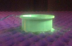
Figure 1: Fluorescent dyes, used in conjuntion with a black light, are more sensitive to small defects.
Welding and nondestructive evaluation (NDE) are the yin and yang of the industrial world. They have a very symbiotic relationship. Many welding techniques would not be acceptable if there were no way to evaluate the resulting welds without destroying them. At the same time, if it were not for the wide need for welding, the demand for NDE would be greatly reduced.
As important as NDE is in the welding field, a veil of mystery surrounds it. Even those who have heard of NDE may not be able to fully explain it. So let’s break it down (no pun intended) into simple terms and examine the most common ways of inspecting a weld without destroying it.
One way to classify types of weld defects is to identify those that are open to the surface and those that are not. A crack is one type of defect that is usually open to the surface. A slag inclusion, on the other hand, is a type of defect that most often is closed to the surface. To uncover defects, you need techniques that can reliably detect both surface and subsurface defects.
The trick is choosing the technique that best suits the defect you are looking for. This bag of tricks is called NDE, also known as nondestructive testing (NDT) and nondestructive inspection (NDI).
Many NDE methods exist, and multiple criteria are used to select the appropriate method. For purposes of this article, we will sort the techniques by those that are most appropriate for surface defects and those that detect subsurface defects.
If a defect is on the surface, you should consider using one of the following NDE methods:
If the suspected defect is subsurface, you should use one of the following:
Let’s look at each of these techniques in simple terms.
Have you ever spilled a liquid on the kitchen table and been astounded by how much was sucked in between the table leaves? This action is caused by a physical phenomenon called capillarity or capillary action, the tension between two approximating surfaces of a liquid and a solid that causes the liquid to rise or fall.
Because it takes energy to create a surface, a crack is essentially the creation of two surfaces caused by excess energy or stress in the part. If a surface is cracked, it will draw liquid into the crack by capillary action caused by the interaction between the liquid and the crack. Dyes formulated for different applications and inspection sensitivities can be used to leverage this interaction. These dyes can be either visible (most commonly red) or fluorescent (used in conjunction with a black light).
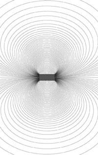
Figure 2: Only ferrous metals can be inspected using MPI.
The type of dye used depends on the size, location, and material type, along with the type of defect that you want to detect. Visible dyes generally are more efficient for jobs with large application areas, such as pipelines, since they can be brushed or sprayed onto the area to be evaluated. Fluorescent dyes generally are considered to be more sensitive to smaller defects. Compared with visible dyes, fluorescent dye inspection requires more equipment and process control requirements (see Figure 1).
Removing the excess penetrant, leaving only the flaw, is one of the most important steps in performing a successful test, as injecting dye into a crack wouldn’t be a very effective inspection technique if there wasn’t a way to draw some of the dye back out before evaluation. To accomplish this, a chemical commonly known as a developer is used to draw the penetrant out of the crack and leave a temporary contrasting background. Developers have several formulations and styles of application.
Eddy current (EC) testing is known as a technique that can “feel.” It involves a probe and an instrument that produces an energy field. When the probe passes over something that changes the energy field, it detects, or “feels,” the change.
If you’ve ever used a metal detector, you’ve performed simple eddy current testing. A metal detector has a loop of wire with electricity running through it which generates a magnetic field that extends into the ground. When the loop passes over a coin, the instrument recognizes that something has caused a change in the energy field, and the machine starts to beep.
EC inspection in industry operates on a similar principle, although the coils can be extremely small and the defects you are looking for are cracks, not coins. When the eddy current probe and machine are in the normal, or null, position, the magnetic field lines are feeling the area underneath the probe, like running your finger through a tub of water. When the probe runs over a crack, the magnetic lines of force sense are disrupted based on the specifics of the crack. It is this change that is detected and measured. Eddy current is also used to locate defects that do not break the surface.
Magnetic Particle Inspection
Magnetic particle inspection (MPI) is performed when you induce a magnetic field in a metallic part (see Figure 2). Only metals that can become magnetic—known as ferrous metals—can be inspected using MPI. Once the piece has been effectively made into a magnet, a fluid or powder with very fine iron particles is placed on the part, and the iron particle will collect where the surface-breaking defect is located. The defect allows the magnetic lines of flux to “leak” from the part.
There are several different ways of applying the electrical current used in MPI to create the magnetic field. To select the proper current, you must consider the part geometry, material, the type of discontinuity you’re looking for, and how far the magnetic field needs to penetrate into the part to locate the defect.
Ultrasonic testing (UT) at its most fundamental level can be illustrated with a hammer, a microphone, and a clock. The hammer makes a noise, the microphone detects and magnifies the returning echo, and the clock times the noise. By calculating the time difference between the strike of the hammer and the microphone echo of the noise—and the speed at which the noise moves through the medium it strikes—you can determine the distance the noise traveled. In technical terms, you’ve just introduced a longitudinal, or compression, wave in the piece being inspected. But wait, that’s not all.
Because energy travels through different materials at varying speeds, a phenomenon called refraction takes place. Imagine picking up a penny from the bottom of a kiddie pool. The actual position of the coin is different from where your eyes and brain tell you it is. That’s because the speed of light changes depending on the environment it’s traveling through. In the kiddie pool example, the light waves slow down when they reach the water, causing the angle at which the light is traveling to skew in relation to the angle that it enters the water, creating an optical illusion. The same thing happens with sound waves.
When a sound is generated, the speed of the sound waves depends on the piece being tested. If the conditions are correct, other wave modes will be generated. Angled sound waves can be introduced into the piece to inspect for defects that are not directly under the transducer by reflecting the signal off of the back surfaces of the item being inspected. If there’s a defect in the path of the sound, the sound will be reflected back to the transducer. This tells you that there is something suspicious in the object being inspected.
Whether you realize it or not, radiographic testing (RT) is an NDE technique that you are probably already familiar with. If you’ve ever been X-rayed, you’ve been the subject of radiographic testing. With an X-ray, a powerful form of energy is used to penetrate the human body and reach a material on the other side that is sensitive to the radiation (the film). After a certain amount of time, a latent image appears imprinted on the film. The image then can be developed into an actual image that shows the density variations of the subject being X-rayed. Areas with higher densities show up lighter because little radiation reached the film. Areas where the densities are lower, such as where a bone is broken, display darker because more radiation reached the film.
The same rules apply for inspecting nonhuman subjects, such as airplanes and pipelines. When exposed to radiation, film placed behind the area to be inspected absorbs more or less radiation depending on the density of the material being inspected. Since areas with less density appear darker, subsurface cracks can be seen as dark lines.
It is important to keep in mind that no “best” method of NDE exists. The most effective and efficient method for evaluating one part may be completely inappropriate for evaluating another. The area that you are inspecting and the type of defect you are looking for are the primary factors that determine which NDE methods are best for the job.


The Welder, formerly known as Practical Welding Today, is a showcase of the real people who make the products we use and work with every day. This magazine has served the welding community in North America well for more than 20 years.
start your free subscription
Easily access valuable industry resources now with full access to the digital edition of The Fabricator.

Easily access valuable industry resources now with full access to the digital edition of The Welder.

Easily access valuable industry resources now with full access to the digital edition of The Tube and Pipe Journal.

Easily access valuable industry resources now with full access to the digital edition of The Fabricator en Español.
In this episode of The Fabricator Podcast, Caleb Chamberlain, co-founder and CEO of OSH Cut, discusses his company’s...