


Weld inspection before you weld
Using procedure qualification testing to standardize welding processes
 |
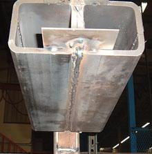
| A welder conducts a GMAW fillet weld test. |
While patrolling a shop floor playing "parameter police," a welding inspector may commonly hear questions like "Why can't I run my machine above XXX wire feed speed?" or "XX volts?"
Welding parameters aren't guidelines merely plucked out of thin air; they are developed and determined after much trial and error. By standardizing the welding procedures you use to manufacture your products, you'll have a model that everyone can turn to for quality assurance.
Procedure Qualification Options
Procedure qualification can be performed in one of three main ways:
- Prequalified Joint Procedures. As the name suggests, prequalified procedures have been tested in advance. Although they're convenient to follow, requirements still must be met. For example, one requirement that often is overlooked or misunderstood is that the procedure must be written. Just pointing to the "good book" isn't nearly enough. Written requirements are laid out
clearly in the applicable code or specification.
For this type of procedure qualification, the American Welding Society (AWS) has determined that, within a given set of circumstances, additional testing is not required.
- Prototype Testing. Although initially economical, prototype testing can be limiting because only those conditions that are tested can be qualified. Any changes require additional testing, which can change the economics of prototype testing significantly.
For example, off-road, agriculture, and construction equipment manufacturers often qualify a process through "push" testing—building a structure, documenting the entire fabrication process (joint by joint), and submitting the structure to several destructive tests. When the structure survives the test requirements, the procedure is qualified. As the component goes into production, all conditions used in the initial test must be maintained during fabrication. Significant changes in production can require additional testing.
- Procedure Qualification Testing. Procedure qualification testing initially can be costly and time-consuming, but it can be used to develop standard weld procedures that cover all joints, consumables, and positions (conditions) used in production.
Procedure qualification testing is a test or series of tests that are performed, documented on a procedure qualification report (PQR), and then turned into a weld procedure specification (WPS) or a series of them.
Procedure Qualification Testing: The Basics
In procedure qualification testing, you may find it helpful to try to complete all testing using readily available resources. Completing testing on one groove weld typically qualifies all groove types and fillets.
Changes in essential variables, however, often require additional testing. For example, in the off-road, agriculture, and construction equipment manufacturing industry, customers often require fillet welds to obtain penetration beyond the root, typically 1.5 millimeters. Many codes and standards require penetration to the root, "... but not necessarily beyond ... ." These same books also may say something like "... joint penetration ... beyond the root ... determined from a significant number of cross-sectioned samples ... ." With an additional customer requirement such as this, you may need to complete both groove and fillet weld testing when creating a standard WPS.
Standard weld procedure testing requires the following samples:
- One test plate for each position
- One test plate for each process
- One test plate per wire type and diameter
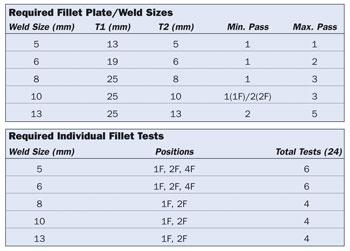
But if your customer requires additional fillet weld testing, you must complete the following:
- One test plate per position (as per standard weld procedure)
- Two test plates per fillet size (one single pass, one multipass)
More Customer Requirements: An Example
Crenlo LLC, a cab and canopy manufacturer based in Rochester, Minn., supplies to off-road, agriculture, and construction equipment manufacturers. The company welds grooves in the flat (1G) and horizontal (2G) positions, and fillets in the flat (1F), horizontal (2F), and overhead (4F) positions. The shop runs on a bulk 90 percent argon/10 percent CO2 mixture and typically uses a 0.035-inch-diameter ER70S-6 filler metal. After consulting a wire manufacturer and other industry professionals, Crenlo engineers determined that a 550-in.-per-minute (IPM) wire feed speed (WFS) and 27 volts should yield the best results.
Let's say you want to develop a weld procedure for gas metal arc welding (GMAW) high-strength, low-alloy (HSLA) carbon steel. You need to develop this procedure for both groove and fillet welds.
First you should know what a test sample will look like and how many samples you're going to need.
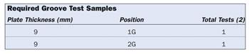 |
| Figure 1 |
For the groove welds, use one test sample for the flat (1G) position and one for the horizontal (2G) position (see Figure 1).
 |
| Figure 2 |
For fillet welds, you'll need samples in the flat (1F), horizontal (2F), and overhead (4F) positions. You'll also need a sample for each weld size, and on that sample you'll weld a single-pass fillet on one side and a multipass fillet (if applicable) on the other. In this case, you'll want to qualify 5- through 13-mm fillets (see Figure 2).
So that's a total of two grooves and 24 fillets—26 tests. What if you want to qualify a higher WFS? According to most codes and standards, 550 IPM qualifies in the range between 495 and 605 IPM. If you want to run a WFS at 650 IPM or more, you'll need to do another 26 test samples. The same applies if you want to use a 0.045-in.-dia. wire, a cored wire, or change another variable
Standard weld procedures are fairly labor-intensive, but the finished WPS will be out of the way and ready to be applied across the board whenever you encounter similar essential variables.
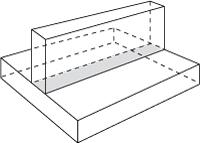 |
| Figure 3 A T joint is used for fillet welding. |
Performing Qualifications
In procedure qualification testing, you'll encounter two main types of qualifications: fillet weld and groove weld.
Fillet Weld Qualification. Fillet weld qualification is pretty straightforward (see Figure 3). For each weld size, make a single-pass fillet weld on one side of the test plate and a multi-pass fillet on the opposite side (see lead photo).
Then simply cut and etch the sample as required in your code or standard and document the results with a digital camera. Use caution when dealing with etching solutions. Strictly follow the instructions and safety requirements laid out by your code or standard.
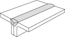
Groove Weld Qualification. As previously mentioned, it may be beneficial to use materials readily available in your shop for your testing. For example, if your shop uses a lot of tubing, you can use sections of 4-in. by 4-in. by 3/8-in. tubing for your groove testing (see Figure 4). The tubes, laid side by side, can create a good flare V groove, and you won't need to bevel the plates or fabricate separate backing (see Figure 5).
 |
| Figure 4 This 4-in. by 4-in. by 3/8-in. tubing is used to weld a flare V-groove test plate in the overhead (4G) position. |
If you use tubing, watch where you place the tubing's welded seam. You don't want it to be located in such a way that it will influence your bend and pull tests. If you place the seams face-to-face, you'll be sure of their location and know that you'll cut them out later.
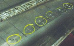
After you've tacked your samples together, always, always, always mark each coupon with a steel stamp. For example, you can use a two-digit number for the sample and 1 through 6 for the individual coupon, increasing in number in the direction of the weld (23-1, 23-2, 23-3, and so on) (see Figure 6). These will be cut from the finished weld later.
Next collect and log all required data per pass, by sample: preheat and interpass temperatures, WFS, voltage, travel speed, electrode stick-out, everything. This system will help you if you're left with a pile of bent and broken coupons and have to figure out what went wrong. That's no time to wonder if you have the right coupon.
 |
| Figure 5 This 4-in. by 4-in. by 3/8-in. tubing is used to weld a flare V-groove test plate in the overhead (4G) position. |
Once you finish welding, perform the first required test: visual examination. All test samples must meet visual acceptance criteria first. If any test sample (fillet or groove) is not visually acceptable, you must discard it. Figure out why it wasn't visually acceptable, correct your process, and make another test sample. Never continue testing on a sample that isn't considered visually acceptable.
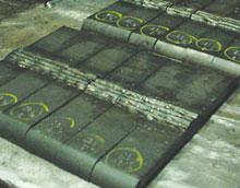
Your code or standard may require radiographic evaluation. If so, perform this next. Remove all portions of the tube that don't make up the test sample, clean them up, and ship them off (see Figure 7). If you use tubing, this can require a lot of whittling — hopefully you're good with an oxyfuel torch. As with visual evaluation, if your test samples don't pass radiographic evaluation, don't take additional action on the test sample. Figure out what went wrong and make a new test plate.
 |
 |
| Figure 6 Mark each test sample's coupons with a steel stamp so you can trace each coupon back to its corresponding test. |
Figure 7 This test sample has been removed from the tubing and is ready to be cut with a saw. |
After you successfully complete these tests, you'll need to start cutting your individual coupons. Your code or specification will dictate exact coupon size and location. Typically, you'll need four coupons for bending and two for tensile testing. Next, move on to etch testing.
Bend and tensile testing comes next. Bend testing equipment is fairly inexpensive and often can be fabricated in-house; documentation is on the market for the equipment's dimensional requirements. Tensile testing equipment isn't as economical, but many companies can perform this type of testing.
Finally, collect and document all test data on a procedure qualification report (PQR) and develop your WPS per your code or standard. Educate your inspectors, supervisors, and welders about the allowed parameters and the need to stay within them.
Although many steps are necessary to complete procedure qualification testing, this process will help ensure that your WPS meets the requirements of the codes and standards you create product to and will serve your company and customers for years to come.
Paul Cameron is a weld engineer, a certified welding inspector, a certified welding educator, certified to ASNT/VT Level II, and member of Practical Welding Today's editorial review committee. He can be reached at 4403 5th St. N.W., Rochester, MN 55901, 507-269-7142, pwcameron@charter.net, www.pwcameron.com.
About the Author

Paul Cameron
Braun Intertec
About the Publication
subscribe now

The Fabricator is North America's leading magazine for the metal forming and fabricating industry. The magazine delivers the news, technical articles, and case histories that enable fabricators to do their jobs more efficiently. The Fabricator has served the industry since 1970.
start your free subscription- Stay connected from anywhere

Easily access valuable industry resources now with full access to the digital edition of The Fabricator.

Easily access valuable industry resources now with full access to the digital edition of The Welder.

Easily access valuable industry resources now with full access to the digital edition of The Tube and Pipe Journal.

Easily access valuable industry resources now with full access to the digital edition of The Fabricator en Español.
- Podcasting

In this episode of The Fabricator Podcast, Caleb Chamberlain, co-founder and CEO of OSH Cut, discusses his company’s...


