


President
Editor's Note: This is the first in a series of seven articles that identify and define the need for a new theory for the net shape processes (of which draw forming is one) and that explain the general content and configuration that new theory must have.
Net shape manufacturing is the manufacturing of piece parts in dies and molds. Draw forming is clearly a net shape process. These net shape processes contrast with the non-net shape processes such as machining, assembly, and welding. The net shape processes have been enigmatic because practitioners know they are different, but just how they differ from the non-net shape processes and what to do about those differences have not been clearly articulated.
The longer and more definitive definition is the subject of this series of articles. This first article focuses on why the processing activities for draw forming must be focused more intensely on level II processing functions than they are for non-net shape processes. This is the first of the seven differences that set apart the net shape processes from the non-net shape processes.
Many of the technology advances in the general field of manufacturing have not been as beneficial to draw forming as one would expect. All too often methods proven to work for non-net shape applications, such as lean manufacturing, statistical process control, just-in-time, and Six Sigma, have not resulted in the expected benefits when applied to draw forming.
This does not mean that those methods have no place in draw forming operations, but it indicates that the way they are applied in draw forming might not resemble how they have been applied before, and successfully, in other industries. What is missing is a coherent, net shape-specific theory on how to design the processes for new net shape (draw formed) parts.
The net shape processes mostly are based on borrowed technologies that were developed for other manufacturing processes. The success has been mixed and often disappointing.
Often when a new high technology is being introduced, an old-timer will stand up and say, "But draw forming is different," only to be put down as nonprogressive and uncooperative. What he is really trying to say is that there are processing issues in draw forming that the new technology cannot accommodate as being presented.
Unfortunately, he is unable to articulate his concern in engineering terms because the necessary engineering terms do not exist. The technical "theory" for his net shape process has never been developed. So he is written off, but he is right that draw forming is different.
The root of the problem is that all the net shape industries have evolved by borrowing technology from the non-net shape industries and adapting the technology through experience. The net shape processes do not have a processing theory of their own.
There is considerable justification for the situation. The application of the mathematics describing the operating physics is difficult. Until the advent of computers, it was unrealistic even to try to apply the mathematics except to the simplest of processes. Even the geometrically simple aluminum beverage can took 20 years of development. But those days are gone. We now have the computers we need, and we also have the understanding of how the processes work.
The net shape industries can realize the full potential of net shape processes only after they have developed a scientifically valid and engineering-focused theory of their own that is well-articulated, widely understood, and can be communicated to industry members within the vernacular of the theory.
The net shape processes differ from the non-net shape processes in seven significant ways:
This article addresses the first of these: level II processing. Future articles will address the remaining characteristics, with one article being devoted to each characteristic.
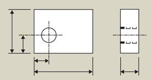 |
| Figure 1 This simple block with one hole illustrates the activities for processing a non-net shape part. |
Processing is the set of activities whereby a fabricator defines the sequence of unit operations needed to transform the sheet metal into a salable piece part, along with a basic description of each of those operations and how they will work. The simple part shown in Figure 1 illustrates the process.
Level I Processing. First the processing engineer must determine which unit operations will be performed on the workpiece. For the part in Figure 1, these might be:
The processing engineer must calculate how long each operation will take and establish the manufacturing cost and equipment loading. He also must estimate the cost of any part-specific tooling, such as the drilling fixture, and estimate the lead-time required to get it built. The time required for the drilling operation consists of the time to get the part from the tub, place it into the fixture, clamp it in, actuate the machine, wait for the drilling to happen, unclamp and remove the part, and place the part into the shipping container.
Except for the feed and speed of the actual drilling operation, all of these activities are intensive in industrial engineering. Even the calculation of the spindle speed and the time for the drilling cut are industrial engineering functions once the cutting feed and speed have been established. These industrial engineering functions are level I processing functions.
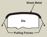 |
| Figure 2 Pulling forces (arrows) put the sheet metal into plastic straining so it will take the shape of the die face. |
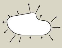 |
| Figure 3 The forces on the edge of the part being formed in the draw die need to be different at each location around the perimeter as indicated by the lengths of the arrows. |
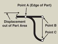 |
| Figure 4 When metal must slide out of the part at point A, on the perimeter there must be additional material between points A and B that gets stretched into the S shape between points A and C. The stretching achieves the required pulling force, and the difference in lengths (i.e., AC — AB) after stretching must be equal to the amount of material that must displace out of the part at that point. |
Level II Processing. However, the actual feed and speed are the critical engineering specifications for making the hole. If energy is not applied correctly to the material, the chip will not be removed, and the hole will never happen. Even if the hole is achieved, it will not be made efficiently if the feed and speed are set incorrectly.
The feed and speed, along with the cutter material selection and cutter geometry, are the engineering criteria for the process of applying energy to the workpiece to cause it to change from what it is to what the fabricator wants it to be. This is an energy application process within the unit operation and is materials science- and mechanical engineering-intensive. Therefore, determining how to design and control the process to apply the energy within the unit operation is a level II processing function.
There is a significant difference between non-net shape processing functions and the net shape processing functions, and that difference is primarily in the ratio of effort exerted in the level I and level II activities. While the level II activities for non-net shape processes are trivial and usually are standardized, level II activities dominate net shape processing. For example, a large draw formed sheet metal part such as an automobile door usually requires the following unit operations:
The speed and cost of the press line are about the same for any other part that might run through it, and the dies for the door panel cost about the same for any door panel. The processing engineer has to make adjustments only for specific differences that are unique to this particular door panel shape. The level I processing issues are much more templated (or standardized) for the net shape processes than for the non-net shape processes.
But then it gets more interesting when the level II issues are addressed. The level II issues involve the application of energy within the draw forming operation to cause the flat piece of sheet metal to change into a door panel. The process is to drape the sheet metal over a form machined into the die faces, which is the shape of the door panel, and pull on the edges to stretch the material until it conforms to the form of the die (see Figure 2).
If these edge forces are too small, the formed sheet metal will try to return to its original flat condition; if they are too great, the sheet metal will tear apart. Very few parts, even the example door panel, are as simple as the illustration in Figure 2, so the practical problem is more complicated than what the illustration might suggest.
Also, the forces are not the same in all directions throughout the part. So the edge pulling forces usually have to be different at all the different locations around the edge (see Figure 3).
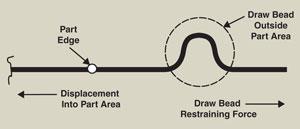 |
| Figure 5 When material must slide across a part's edge into the part, the force on the part edge is achieved with a draw bead that causes a resistance to the sliding motion through friction and bending. |
As the sheet metal is stretched, it becomes longer than what it was originally, but it also is being wrapped onto a form that usually has a longer line length than the original piece of sheet metal. The desired end result might require that some material slide out of the part past the edge or that some material slide into the part across the edge of the part point (see Figure 4 and Figure 5).
The shapes and their dimensions in Figures 4 and 5 must be established at each point around the perimeter of the part to focus energy properly onto the workpiece.
Level I and level II processing activities are the first real and significant differences between net shape processes and non-net shape processes. These differences demand different organizational structure and staffing, different computer systems, different skills for the processing engineers, and a different management philosophy.


The Fabricator is North America's leading magazine for the metal forming and fabricating industry. The magazine delivers the news, technical articles, and case histories that enable fabricators to do their jobs more efficiently. The Fabricator has served the industry since 1970.
start your free subscription
Easily access valuable industry resources now with full access to the digital edition of The Fabricator.

Easily access valuable industry resources now with full access to the digital edition of The Welder.

Easily access valuable industry resources now with full access to the digital edition of The Tube and Pipe Journal.

Easily access valuable industry resources now with full access to the digital edition of The Fabricator en Español.
In this episode of The Fabricator Podcast, Caleb Chamberlain, co-founder and CEO of OSH Cut, discusses his company’s...


