


Contributing Writer
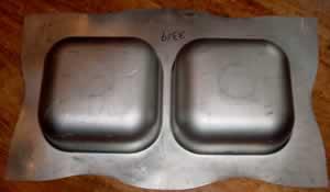 |
| Figure 1 Double drawn stainless steel sink Sink photo courtesy of Polarware. |
Have you ever looked at a deep-drawn double-bowl sink and wondered how it's made? After all, one deep-drawn shell is right next to the other. Where does the metal come from to achieve the height?
Figure 1shows a classic double-drawn sink that has not been trimmed, punched, or flanged. So what's the secret? Quality material combined with near perfect metal flow control results in success. That's the ticket. It sounds easy, but it's not, especially considering all of the controlling factors. This article focuses on a few of these factors, as well as some old and new methods used to control metal flow and to produce difficult deep-drawn geometries.
Numerous problems are associated with deep drawing. Regardless of what method you are using, the following two conditions can and will occur.
 |
| Figure 2 |
1. Die Deflection
It is a grim reality that anytime a die is subject to pressure, it will deflect, bend, and twist. During drawing, deflection in the pressure pads and die face may cause loose or tight areas between the die face and draw pad, resulting in a loss of metal flow control. This loss may cause undesired wrinkling, loose metal, oil canning, surface defects, and fractures. Some of the underlying reasons for excessive deflection may be:
Insufficient draw pad and cavity thickness
It's simple physics—thinner draw pads and cavity blocks, when subjected to force, will deflect more than thicker pads and blocks.
Poorly maintained cushion pins
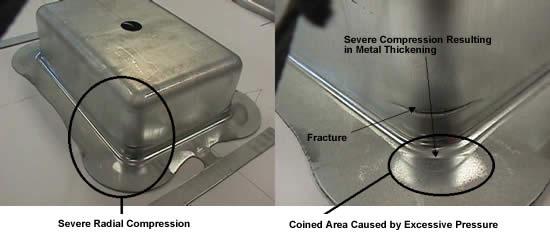 |
| Figure 3 |
Cushion or air pins should be large enough to withstand the needed pressure and precision-machined to an equal length. All too often these pins get mashed, bent, and deformed during the drawing process, which results in die deflection.
Poorly maintained press cushions
 |
| Figure 4 |
The press cushion also must be maintained precisely. The cushion plates must be very thick to resist deflection,; machined flat; kept clean; and free from any surface defects, such as dents or divots.
Poorly adjusted equalizer blocks
Equalizers are spacer blocks mounted between the die face and pressure pad that function to maintain a uniform gap for the metal to slide. If the equalizer blocks are shimmed excessively, severe pressure pad and die face deflection can occur (see Figure 2).
Inconsistent, nonuniform pressure distribution under the draw pad
Poorly maintained press cushions, stand-alone nitrogen springs, coil, and urethane springs are notorious for applying uneven pressure distribution to the pressure pad.
Changes in the metal's thickness during drawing
 |
| Figure 5 Severe Press and Die Deflection Image courtesy of Hydraulico. |
Very little attention is given to the fact that the metal's thickness changes during the drawing process. Metal in compression can thicken, while metal in tension can thin out. Excessive thickening can cause the pressure pad to separate from the die face, resulting in a loss of metal flow control. This is a problem, especially when drawing a rectangular shell.
Excessive thickening in the drawn shell's radial portion can cause the pressure pad to prevent the metal from feeding, which can cause the metal to fracture (see Figure 3Remember that metal in compression already has a resistance to flow. Clamping down with more pressure pad force in the radial area only creates a greater resistance to flow.
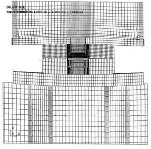
Presses also deflect. When the press deflects, so does the die. Severe press deflection also can result in a loss of metal flow control. Different presses deflect in different manners. For example, gap- or C-frame presses deflect in a fashion similar to a C clamp. Straight-side orboxpresses deflect from the center of the bolster outward (see Figure 4).
Severe press deflection can also result in severe die deflection, which may cause a loss of metal flow control (see Figure 5).
 |
| Figure 6 Image courtesy of Hydraulico. |
Let's begin by accepting and understanding that both of the preceding conditions are going to happen. Rather that trying to eliminate deflection, the better solution is to engineer the dies to compensate for deflection and changes in metal thickness.
Draw Spotting
One of the oldest methods used is called draw spotting. Draw spotting, often referred to as a running spot, is the process of grinding the blank holder or die face with respect to compressive thickening and tensile thinning that will occur during the drawing process. In the corners of a draw and anywhere there is a radial profile, the metal will be in compression. Compressed metal trapped between the die face and a blank holder will thicken during the drawing process.
Grinding the die face or blank holder with respect to compressive thickening will help to reduce the resistance in the drawn-shell corners and allow greater blank holder force to be applied to the blank that will form the drawn shell side walls. Too often the thinking is if the part is flat, a perfectly flat blank holder can be used. Flat blank holders are suitable as long as they are draw-spotted to metal flow conditions. Draw spotting can also assist in balancing metal flow. This process also is referred to astuningthe pressure pad.
 |
| Figure 7 Image courtesy of Hydraulico. |
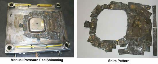
Manual Pressure Pad Shimming
By adding an additional top plate to the pressure pad and placing shims under the pad, the metal can be squeezed with different forces within the blank perimeter. This time-consuming process deflects the top plate with respect to the shims and often requires reshimming for different presses, pressure systems, forming speeds, and frictional values.
The number of shims as well as the placement of each shim can result in a draw pad nightmare. Figure 6shows a typical shimming for a single-bowl deep-drawn sink. This shimming does not allow for the pressure to be changed during the press stroke.
Electronic Shimming
Imagine having the ability to change the blank holding pressure anywhere within the drawing punches' entire perimeter atany pointduring the press stroke. Now imagine having the ability to control these pressures electronically simply by pushing a few computer buttons. What you have just imagined is a reality. It's called electronic shimming.
Electronic shimming works by hydraulically raising and lowering special blocks inserted into the pressure pad. These blocks deflect a special top plate to squeeze the material or let it go during the stroke. This gives the die setup person or tool technician an infinite variety of forces and pressures. Because this system is fully programmable, items like press and die deflection can be compensated for quickly and easily. Figure 7shows a typical electronic shim layout (top plate removed).
Most deep-drawn sinks and cookware items, such as pots, are made using an electronic shimming system. However, as the automotive world changes to forming high-strength steel, we need to look at alternative forming methods. A conventional pressure pad and draw punch may not cut the mustard, especially for difficult deep-drawn geometries. Controlling metal flow is critical.


The Fabricator is North America's leading magazine for the metal forming and fabricating industry. The magazine delivers the news, technical articles, and case histories that enable fabricators to do their jobs more efficiently. The Fabricator has served the industry since 1970.
start your free subscription
Easily access valuable industry resources now with full access to the digital edition of The Fabricator.

Easily access valuable industry resources now with full access to the digital edition of The Welder.

Easily access valuable industry resources now with full access to the digital edition of The Tube and Pipe Journal.

Easily access valuable industry resources now with full access to the digital edition of The Fabricator en Español.
In this episode of The Fabricator Podcast, Caleb Chamberlain, co-founder and CEO of OSH Cut, discusses his company’s...


