


Avoiding common bending problems with common sense
Match tool design with bending application
As we strive for simplicity in solving manufacturing problems, we are captivated and enthralled with the flash and glitter of the newest gadgets. Whether by clever marketing or our innate desire to have the latest and greatest newfangled technological gadgets, the outcome is the same. We not only believe that bigger and badder is better, we positively crave it and will generally stop at nothing to justify it.
When sourcing technology for new manufacturing projects, we want it all. It seems to be in our nature. Not only must the equipment produce good, accurate parts quickly, but it must look good doing it. We want, or need, equipment that is bigger, badder, and better than our competitors' technology.
These days manufacturers tend to run lean, and competition is intense. The environment is fast-paced, short-handed, and frantic. We're all trying to do more with less and in less time, and when we're looking for a technology to help alleviate some of the pressure, an emotional reaction rather than a reasoned response usually wins.
Rather than go with the gut instinct and our need for the flashiest solution, we should try to use a methodical, calculated approach.
All of the factors that come into play in a bending operation are driven by the application itself. Do you have just a few bend radii and a small number of tube ODs, or do you anticipate a large variety of bends? Are they simple or complex? What is the total number of finished parts you expect to produce in a week, a month, or a year?
These factors, among others, drive the tooling options and design. Simply stated, garden-variety tooling offers little versatility with few options, but it is a good first step if your application can be formed this way. More complex designs have advantages, but too much complexity can adversely affect the success of the bending application.
Give similar thought to your bending machine. Its main function is to provide a rigid, stable platform for the tooling. It also assists in gripping the tube by providing the necessary pressure. Don't be misled, though. All the pressure in the world can't make up for poorly designed tooling. In fact, too much pressure will shatter the tooling. The workpiece dictates tooling design and bender selection, and all must be matched well or they simply will not work together to produce parts successfully.
Tooling Tales
All tube bending operations depend on the tooling. While the majority of applications can be formed with simple, commodity-type bend tooling and methods, many cannot. It is essential through proper applications analysis to match the tooling type and design with the workpiece requirements.
Matching the bending method, bender features, and type of equipment to the tube's requirements will help you avoid costly mistakes and production nightmares. Focus on the fact that successful tube bending is a complex operation because of continuously changing variables that must be manipulated into a workable formula. Simply stated, the harder the problem, the more simple the solution must be.
Assume that rotary draw (mandrel) bending has been determined to be the best method for your application. To lay the proper foundation for this, you must at least become familiar with some of the common mistakes with regard to the bending equipment.
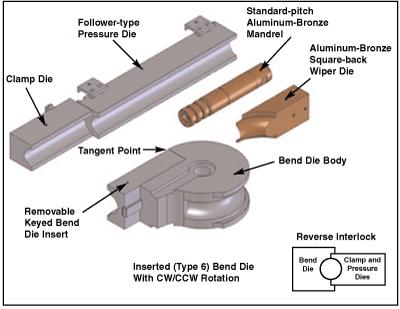
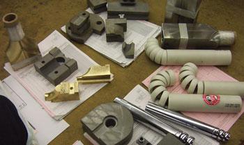
Figure 1 Bend tooling by design can be as simple or elaborate as the application it is intended for.
Your application determines basic criteria for the bender, and the most feasible, profitable manner to produce it. These criteria include the following:
- Size and wall thickness of the workpiece
- Materials to be bent
- Number of bends in the part
- Proximity of the bends to one another (distance between bends, if any)
- Plane of bend relationship to one another
- Production rates
- Finished part tolerances (such as for wall thinning, ovality, and point-to-point dimensions)
- Centerline radius of the bends
- Initial cost of equipment (plus training, service, support, repair parts, and tooling)
- Return on investment
Bear in mind that the bender needs to have enough power for the job and enough finesse to align the tooling properly to get the job done, and it must have both in equal measure. A machine with its tool-mount surfaces knocked out of adjustment will be less productive, and if it is not corrected, it will ruin the tooling.
In this case, bigger is not necessarily better. Bigger might be stronger and more rigid, thus providing a more stable platform for holding the tooling in alignment, but if you don't take into account the configuration of multiple-bend parts, you can get into trouble with machine/part interference if the machine has a large frame and footprint. Furthermore, adapting small-OD tooling to a large-capacity bender has a substantial cost disadvantage.
Bender Basics
Be very clear on what the present and future requirements are. Obviously, the choice of machine will differ radically from a job shop environment to a fully automated production cell.
A CNC machine is not needed if you are making simple, single-bend parts. If the parts have no more than one centerline radius, it is not necessary to stack multiple tool sets on the machine. An exception to this would be if the bends have little or no straight tube length between bends and you need to stack the tooling to facilitate bending with no tooling changeover.
Machine features affect equipment cost, so be certain they are necessary. Remember, keep the system as simple as possible.
Before making a purchase, know where to go for support, service, part repair, and operator training, not only at a machine runoff but after the sale as well. Familiarize yourself with the documentation received at the time of purchase and how accurate and helpful this documentation is to the maintenance department.
Knowledge is power when considering used equipment. If you don't know what you're looking at, find someone who does. Spending money for a consultant isn't a bad idea if you're dealing with unfamiliar makes and models. Purchasing a plane ticket is cheaper than replacing a boat anchor.
The bottom line is that you will invest a substantial amount of money, so do your homework, spend the money once, and spend it well. Good research is an investment, while a large impulse expenditure is a disaster.
More About Tooling
Not all rotary draw bend tooling is created equal. It is absolutely vital that you educate yourself to make the best use of your tooling budget. If you do not understand the bending process, bending equipment, and part prints, you should not attempt to source bend tooling. Leave this job to an experienced professional.
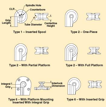
Figure 2 Bend dies differ in cost based on the complexity of their design and the amount of support they can provide.
The variables affecting tooling design are numerous. Confusion increases exponentially if the person gathering supposedly comparative quotes does not use adequate information and isn't experienced enough to competently evaluate suggested tooling options. It can be disastrous to go with low-priced tooling that has no versatility; it can be equally disastrous to think that bigger and badder is better.
Bend tooling by design can be as simplistic or elaborate as the application it is intended for (see Figure 1). As a basic design rule, versatile tooling costs more to design and more to produce.
The bend die can be as simple as the type 2 one-piece (see Figure 2), the most cost-effective die available. Its limitations, however, can be a problem for some part configurations.
The principal limitation of this configuration is that the grip area of the die is not removable, so the grip length is set and nonadjustable. The upside is that this die is cost-effective and strong. In the event that the die is constructed with a grip length of, for example, four times the tube diameter (4D), this would be the minimum straight length of tube that two adjacent bends could have. Generally, the next option most fabricators consider is to go shorter on the grip length for versatility without cost increase.
As the grip length decreases, the amount of pressure needed to hold the tube securely increases, which can cause tube surface marking and increase tooling wear. In the instance of very short grips, an aggressive surface can be machined into the tube groove surface. These can be fine or coarse radial serrations (directional buttressed grooves). Many grades of flame-applied ceramic carbide coatings are also common in the tube groove of the grips.
A machined-tapered knurl pattern provides optimal grip without the radial marking typically associated with serrations. One drawback to these grip finishes is cost. Another is increased die wear, because the die grips the tube with less surface area. It is a better option to consider a bend die design that has bolted-in and removable grip areas, such as the type 1 and type 6 dies.
The first time that you have to replace an entire bend die because the serrations in the tube groove of the nonremovable grip are wearing will generally be the last time you permit it to happen. Note that the optional reverse interlock alignment feature shown in Figure 1 can be added to all tool designs shown. The advantage is obvious, as is an understandable increase in cost. Note the simple construction of the type 1 die, also called an inserted spool die (Figure 2). This is cheaper to make than the type 6 die. The difference in these two designs is a matter of support. On the type 1 die, at least two-thirds of the length of the removable grip should be supported from the bend die body. A type 6 die can support the total insert length if necessary for additional ridgidity.
This said, if the overall diameter of the bend die itself gets smaller because of a decrease in centerline radius, less of the insert is supported. Under extreme conditions the insert can actually break from the pressure exerted from the clamp die. In this situation, a type 6 die is the next option, as the insert is fully supported from the bend die body.
Because these type 1 and type 6 dies have a removable grip design, the same bend die body can be used for various insert lengths and finishes, including compound clamps to grip a previous bend when no straight is available. In well-supplied tool cribs, a large inventory of, for example, 2.0-in.-OD bend die bodies with different centerline radii dimensions are designed to accept all present and future bend die insert lengths and finishes.
The initial cost per tool is more, but the cost saving from not having to buy multiple inserts of the same length for every bend die body and interchangeability of the tooling may offset the higher initial cost.
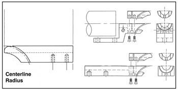
Figure 3 A wiper die may be necessary, as well as multiball internal mandrels, to prevent tube wrinkling.
Selecting a Bending System
The bender type you choose affects your bend die cost and design substantially. Most rotary draw machines, with the exception of some stacking designs, are engineered to have a standard centerline height for the tool set.
The term centerline height is best defined as the dimension, measured vertically, from the machine surface (or die boss) that the bend die mounts on to the center point of the tube groove.
This means several things in regard to tool design. First, centerline height establishes the overall height of the tool itself. Also, the die often must be symmetrical about its centerline, which in turn means a larger piece of material for the die.
Most rotary draw benders operate either clockwise (CW) or counterclockwise (CCW) as they bend the tube. It is common for a bent part configuration to dictate the rotation required to form the tube without machine/part interference (a collision of the tube with the bender). In extreme situations, both a CW and CCW bender may be required. In both cases, the tooling must be reversible and have machine mounting (counterbore and drive keyways) on the top and the bottom. Some specialty machines bend CW and CCW. Such machines are extremely sophisticated and priced accordingly.
Another way the centerline height affects die design and cost concerns rigidity of the bend die as it's mounted on the bender. A rule of thumb is that if the centerline radius of the bend die is the same as or less than the centerline height of the bend die, the bend die stability under load in the bend cycle will be compromised.
The typical design remedy for this is to incorporate an integral platform on the die to give it a larger-diameter footing on the machine. In severe situations, it may even be necessary to bolt the die down to the bender through this platform in addition to the standard machine bend die stud mounting. The tighter the centerline radius is and the larger the tube diameter gets, the worse this condition will be. The more options that the bend die must have not only substantially drives up its cost, but can also adversely affect its design and cause premature failure and breakage.
Consider the possibility that a bend die needs a platform because of a tight centerline radius compared with the centerline height. It must be stacked (for an application with more than one centerline radius) or reversible for dual rotation (CW and CCW). Also imagine that this hypothetical tube required to be bent has two bends adjacent to one another with no straight tube to grip on. This means this die needs a removable insert that must extend to the tangent point of the bend die (the point where the grip area stops and the bend area begins) because of the compound clamping required for the second bend on the next tooling set stacked on top.
Last but not least, two other issues now come into play in this scenario. As the tube diameter increases, the centerline radius decreases, and the tube wall gets thinner. Not only are multiball internal mandrels required, but a wiper die also is needed to prevent the tube from wrinkling (see Figure 3).
Now let's look at the hypothetical tool setup. As the bend die rotates to form a bend, the tube sticking out of the clamps rotates around toward the wiper and the machine bracket holding it. Based on the maximum degree of bend in the part, the back of the bend die and its insert must be machined with enough clearance to prevent the collision that would take place. In severe situations, the wiper and/or the bender's wiper bracket would need to be cleared in this area also.
The extra material and machine-hours spent clearing all that material out of the section of the bend die that would collide with the wiper die increase the cost, of course, but here's the real kicker: Material removal from the back of the bend die or insert causes the bend die to cost more and ultimately results in a smaller, less stable, more fragile bend die that is more likely to fail (and probably at the worst possible time).
Avoid the common mistake of designing these problems into your tooling. Tooling design should get this elaborate only when the application demands it. Usually special applications that walk the fine line of feasibility require tooling that does the same. Before casually requesting all the bells and whistles when comparing tooling quotations, consider the simplest solution to your needs first. Base the tooling design on the application the first time and not as an afterthought.
If tooling procurement personnel don't have enough experience to weigh the options, don't understand the machine's limitations, and aren't familiar with everything that goes into producing good bends, tooling choices won't be as good as they could be. That's something to keep in mind before making real-world decisions or simply using the "bigger, badder, and therefore better" line of thinking.
About the Author
About the Publication
subscribe now

The Tube and Pipe Journal became the first magazine dedicated to serving the metal tube and pipe industry in 1990. Today, it remains the only North American publication devoted to this industry, and it has become the most trusted source of information for tube and pipe professionals.
start your free subscription- Stay connected from anywhere

Easily access valuable industry resources now with full access to the digital edition of The Fabricator.

Easily access valuable industry resources now with full access to the digital edition of The Welder.

Easily access valuable industry resources now with full access to the digital edition of The Tube and Pipe Journal.

Easily access valuable industry resources now with full access to the digital edition of The Fabricator en Español.
- Podcasting

In this episode of The Fabricator Podcast, Caleb Chamberlain, co-founder and CEO of OSH Cut, discusses his company’s...
- Trending Articles
1
Team Industries names director of advanced technology and manufacturing

2
Orbital tube welding webinar to be held April 23

3
Chain hoist offers 60-ft. remote control range

4
Push-feeding saw station cuts nonferrous metals

5
Corrosion-inhibiting coating can be peeled off after use
