


Consultant
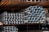
Figure 1: If a fabricator wants to reduce the time it takes to bend tubes, shop management needs to stage raw material close to the bending machine.
Have you ever purchased a tube bender with an expectation that it will bend a certain number of parts per hour, but then find out that you significantly miscalculated the anticipated production rates? The question that needs to be analyzed in such a situation is this: How did I arrive at that number of parts?
Many years ago, when I was an engineer, I purchased a tube bender with a quoted bend time of 10 seconds per part. My part had three bends. Based on that information, I did my calculations to determine how many benders would be required to produce the bent tubes required by the job orders.
Very soon after the first machine arrived, I found that I was really off the mark. My mistake was not determining the total processing time—which was quite different from the bend time. Having made that mistake, I then was challenged to improve the overall processing time so that parts could be completed in the available production time.
These steps helped me—and can help other fabricators—to optimize the performance of tube benders and reduce tube bending cycle times.
The most important issue to remember is that everything that occurs during the bending process takes time. Every second must be accounted for. It makes no difference if it is material loading, adjusting controls, manipulating material in the machine, or unloading.
Every second counts and is part of the total processing time. Determining this number is important before starting any improvement efforts. This will set the baseline, so you know how much you have improved. To determine that benchmark figure:
The first issue to address is the load time (see Figure 1). If the machine does not have automatic loading, then someone has to pick up the material and load it on the machine. This may include pushing it onto the mandrel (if you’re mandrel bending) to the point that the machine grasps the tube or positioning the tube to a predetermined location, such as a mechanical stop.
While this sounds simple, you may have to jump some difficult logistical hurdles to locate and load the material. The goal is to have the straight material in a location where you can easily pick it up and quickly load it.
If the tubing is quite long or is not exactly straight, this becomes a significant force to overcome. It becomes even more difficult during mandrel bending because you have to push the difficult-to-handle tubing over the mandrel. In these cases, it is important to have a locator to place the end of the tube for the start of the bending process.
Another factor that affects loading is whether the pipe to be bent is welded. It is best to keep the weld seam on the neutral axis. This is a bit of a challenge because typically there is weld slag on the inside of the tube unless it has been cleaned off. If you’re using a mandrel, the mandrel may need to have a groove cut in it on the neutral axis to allow the tube to slip onto the mandrel without running into any interference associated with the weld slag.
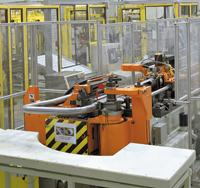
Figure 2: CNC machines automate many aspects of the bending process, but a keen eye always can find room for improvement.
You can order tubing that already has the weld slag on the inside scraped off in the tubemaking process—also called scarfing. Even with the slag removed, however, it is still best to place the tube weld seam on the neutral axis.
On a CNC bender (see Figure 2), the next issue to address is the tube bending time—which includes the travel time of the bender before the first bend, between subsequent bends, and after the final bend. This is typically a set time in the bender. However, on some machines this is programmed differently, which will be discussed later.
If you’re using a manual bender when setting each leg length, the challenge is to move the tube manually to the next location in preparation for bending. Some machines have stops that are adjustable to make this operation more exact. If not, you must measure between each feed to ensure the part is in position for the next bend.
If the machine has no stops, you can speed up the bending process by making simple measuring fixtures that allow you to put the fixture in a location while moving the part to the next location for the next bend. Measuring fixtures can be as simple as a series of pieces cut to the length of the feed required and marked in a way that the operator knows how to use them.
When bending angles in the same plane on a manual machine or pressure bender or when bending to a specific angle, the accuracy is totally in the hands of the person making the bend, unless stops can be set so the operator can bend to them. To ensure all the tubes are the same, this process must be made easy and repeatable. Again, you can make simple angle fixtures to help set this angle.
Another issue that comes into play when making the bend is the amount of springback that may result. This can change with each batch of tubes. If you want a 90-degree bend, you may need to bend it to 95 degrees to compensate for the springback once it comes off the machine.
The engineer needs to work with the operator to set up a chart for each bend to determine the springback so when the part is complete it is within tolerance. Once that’s done, you can bend to the predetermined angle to get the correct part angle.
If you are not making bends in the same plane, you can rely on the CNC machine, because springback compensation is programmed into the control software. However, note that a minimum distance is required between bends, no matter what kind of machine you are using.
If you’re not making bends in the same plane and using manual or pressure bending machines, you will need considerable time to set each angle. In this case, you can make simple fixtures for each angle that allow you to set each angle quickly before setting the machine to make the next bend. Using these fixtures speeds up the measuring process and provides more bending consistency.
Next comes the unload cycle. Once the bending cycle stops, how long does it take to get the part off the machine and put in a rack or bin? You must be able to get to a rack or bin quickly to get the part off and put in the bin. This can be challenging because you likely are working around the cart or rack of material to be loaded onto the machine. However, it is worth the effort to look at this process critically to help reduce the part cycle time.
Most important is to have enough space to pull the part off the machine and load it quickly in a bin or cart. In addition, space must be allocated to load the next tube to be bent.
The finished-part bin should be located as close as possible to the fabricating end of the bender to reduce operator movement. It may make sense to position the raw material on one side at the end of the bender and the cart or bin for the finished parts on the other side. This creates a small workspace for the operator, which will reduce movement as much as possible without being unsafe.
If the straight tube to be bent is long and difficult to handle, you should place the finished-part bin off to the side of the tube bender and locate the cart of straight material in front of the machine. So when it comes time for loading, you pull the tube and push it onto the mandrel—all in a straight-line motion.
These suggestions work for all bender types—CNC, manual, and pressure bending.
CNC benders can produce consistent results, but material is not as consistent. This creates the potential for inconsistencies in the degree of bend in the tubes. First-piece inspection then becomes time-consuming unless you can establish a simple method to do it quickly.
One way is to make a simple fixture that shows if the correct tolerances have been met. You set the part in the fixture and see whether or not the part fits. It’s basically a go/no-go gauge. This measurement fixture—which can be as simple as a plywood structure set to the correct tolerances—can save significant measuring time.
Keep in mind some other factors that can affect total tube bending cycle time:
The downside of this option is having lubricant flowing through the tube once it is placed on the end product. A shop may need to determine a way to clean out the inside of the tube if lubricant is applied?
Of course, such a capability can lead to confusion on the shop floor. Someone might set the machine to a slower speed for a specific material and not mention the change to others. Therefore, if different materials are run at different speeds on a CNC machine, develop a machine chart detailing speed settings for each material type, and then train everyone on how to set the machine.
These tips will help you determine the true tube bending cycle time—incorporating load, bend, unload, and quality check. After that time has been determined, you can accurately figure out how long it takes to bend one part and use that figure for scheduling purposes and costing.
You also can compare this total tube bending cycle time to the time it took before any changes were made. This will give you an idea of the total improvement made.
Do You Need Additional Capacity?
In today’s economy, many metal fabricating companies may need additional capacity but simply cannot afford a new machine. Here are a couple ways to resolve this:


The Fabricator is North America's leading magazine for the metal forming and fabricating industry. The magazine delivers the news, technical articles, and case histories that enable fabricators to do their jobs more efficiently. The Fabricator has served the industry since 1970.
start your free subscription
Easily access valuable industry resources now with full access to the digital edition of The Fabricator.

Easily access valuable industry resources now with full access to the digital edition of The Welder.

Easily access valuable industry resources now with full access to the digital edition of The Tube and Pipe Journal.

Easily access valuable industry resources now with full access to the digital edition of The Fabricator en Español.
In this episode of The Fabricator Podcast, Caleb Chamberlain, co-founder and CEO of OSH Cut, discusses his company’s...


