


President
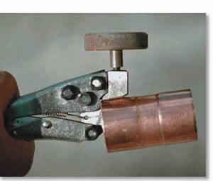 |
| This tool modifies copper fittings by making a shallow impression in the fitting wall, shortening the socket depth to 3/8 in. It should be used only for joints that will be brazed. |
Butt joints between copper tubes can be just as strong as the copper itself if the filler metal is strong enough. This is because all of the load must be carried through the contact area of the two small surfaces at the ends of each piece (see Figure 1). Butt joints typically aren't used to join copper tube because maintaining alignment during brazing is difficult.
Socket joints, on the other hand, are self–aligning during assembly and brazing. In a socket joint, the filler metal doesn't have to be as strong as the copper because the contact area between the tube and socket can be made large (see Figure 2).
When the bonding area is large, the stress in the braze metal is low, so the filler metal can be much weaker than the base metal. Therefore, when you use commercial copper tube fittings that have deep cups, you can use soft solders with tensile strength of about 5,000 pounds per square inch (PSI) successfully to join stronger copper tube with a tensile strength around 30,000 PSI, for example.
 |
| Figure 1 Butt joints between copper tubes can be as strong as the copper itself if the filler metal is strong enough to carry a load through the contact area of the two small surfaces at the ends of each piece. |
A tube joint has to be strong enough to carry loads such as pressure, dead weight, and thermal expansion. If you choose a combination of filler metal and socket depth that makes the joint stronger than the tube, the tube itself becomes the limiting factor in the design.
The strength of a torch–brazed socket joint depends on:
 |
| Figure 2 In a socket joint, the filler metal doesn't have to be as strong as the copper because the contact area between the tube and socket can be made large. |
Using these variables, you can estimate the required depth of insertion with this formula:
Where:
When you solder a copper–to–copper joint, the tensile strength of the copper is about 30,000 PSI, and the shear strength of the solder is about 5,000 PSI. For tube that is 0.065 in. thick, the overlap needs to be 0.48 in., or 8.7 times1 the tube thickness.
 |
| Figure 3 This chart plots the joint strength and shear stress to overlap length for soldered and brazed joints. |
When you braze a copper–to–copper joint with any of the commonly used AWS classifications of brazing filler metals, such as BCuP or BAg, the shear strength of the braze metal is about 25,000 PSI. For a tube that is 0.065 in. thick, the overlap needs to be 0.100 in., or 1.5 times the thickness of the tube.
The relationship between tube thickness and overlap length for brazed and soldered joints are plotted in Figure 3.
To see if theory worked in practice, the author's associates brazed and performed tensile tests on 1 1/2–in. copper tube with a wall thickness of 0.045 in. Joints tested were a butt joint and socket joints with overlaps of one, two, and three times the tube thickness. All specimens, including the butt joint, failed in the base metal.
It isn't news that you need only a small overlap for brazed joints. In a round–robin series of tests in the late 1950s, 10 labs brazed more than 1,200 tensile test specimens. The labs performed these tests on the following with various overlaps:
The results of these tests showed that you don't need a lot of overlap to get a full–strength joint. In all cases, base metal tensile strength was reached when the overlap was twice the thickness of the members (2t). The report was published as American Welding Society (AWS) C3.1–63.
The depth of insertion affects two significant aspects of brazing: the strength of the joint and the ease of brazing it. Although it appears from a strength viewpoint that more overlap is better, overlap beyond two times the thickness of the thinner member (2t) doesn't make the joint any stronger.
In fact, increasing the overlap much more than 2t only makes it harder for you to make a sound joint for the following reasons.
First, the braze metal has to flow uniformly into a small gap between the parts for the entire length and circumference of the joint. One obstacle is that the longer the overlap is, the farther the braze metal has to flow and the more opportunity it has to trap gas, which causes voids in the joint. A sufficient supply of flux and adequately high, uniform heating of the joint promote the flow of the braze metal into the joint, but as overlap increases and the diameter becomes larger, this becomes more difficult.
 |
| Figure 4 This chart shows common copper–based brazing filler metal composition and melting characteristics. |
Second, brazing filler metal begins to melt at a lower temperature than the temperature at which braze metal is fully liquid. This temperature is called the solidus temperature. Just above this temperature, the braze filler is a mixture of solid plus liquid. It is thick and slushy, much like a frozen drink. In this condition, metal doesn't flow easily into a closely fitted joint. Imagine sipping a frozen drink through a small straw quickly –it's difficult!
As the filler metal is heated more, it becomes more completely liquid until it reaches the liquidus temperature. At this temperature, the filler metal is fully liquid and flows readily into the tiny space between the parts. Or, as with our example, the frozen drink now is melted and flows through the small straw easily. Solidus and liquidus temperatures for some common filler metals are shown in Figure 4.
To further complicate the situation, during brazing a small amount of the copper base metal dissolves into the filler metal, and a small amount of the alloying elements in the filler metal diffuse into the copper base metal. When this happens, the chemical makeup of the filler metal changes. This increases the liquidus temperature, and the filler metal turns thick and slushy even though it's hot. Again, thick, slushy filler metal doesn't flow into the joint easily.
Fortunately, this diffusion–dissolution process is slow compared to the time it takes for braze metal to flow into a properly heated joint. However, if the joint isn't heated enough before braze metal is introduced, the braze metal starts out slushy and becomes thicker as you reheat the joint. The longer the joint is at brazing temperature, the more the braze metal composition becomes like the copper itself. This explains why it can be difficult to get a joint to remelt after it's been brazed.
Diffusion isn't all bad, though. Jet engine compressors, for example, are used at temperatures above the melting temperature of the braze metal that holds them together. In this application, the parts are held in a furnace at diffusion temperature for so long that the braze metal is dissolved completely in the base metal and the joint basically is gone, allowing the engine to stay together in service.
Using Solder–joint Fittings When Brazing
If excessive overlap makes getting a sound brazed joint unnecessarily difficult, why does the industry use solder–joint fittings that have so much overlap?
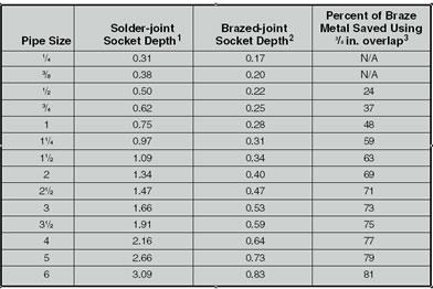 |
| Figure 5 This table shows the socket depth for solder and braze joint fittings and savings using a 3/8–in.–deep socket. |
The answer is simple: lawyers. Ordinary copper and brass fittings are made to be soldered, not brazed. They typically give you 10t overlap or more, which is what is needed to ensure adequate strength if the joint is made with solder (see Figure 5).
Because fittings manufacturers have little control over where their fittings will be used or how they will be joined, the least risky thing for them to do–this is where the lawyers come in–is to make all the fittings suitable for soldering.
Solder–joint fittings can be brazed, but the cup depth can make your life difficult. Fittings with short cups that are designed for brazing are available and are easier to braze than solder–joint fittings, but they typically are special–order items with limited distribution. Contractors who supply these fittings to you face the same liability risks as fittings manufacturers.
When you qualify a Brazing Procedure Specification (BPS) under ASME Section IX, the minimum overlap that will be used in production must be used during qualification. In other words, if the overlap used on the test coupon was 1/4 in., the minimum overlap that must be used in production is 1/4 in. You also should be sure that the production overlap is at least twice the thickness of the thinner part to be joined (2t). This ensures adequate joint strength for production joints.
When you qualify a torch brazer, he or she is limited to the overlap that was used on the test coupon, plus 25 percent. In other words, if the test coupon overlap was 1/2 in., the maximum overlap qualified is 5/8 in. You don't have a minimum overlap, because if you can properly braze a deep socket, you also can braze a shallower socket.
Because you need only a small overlap (2t) to achieve full strength in a brazed joint, you don't need the full depth of a solder–joint fitting. More socket depth just adds to your suffering when you're making a joint. To make matters worse, the bigger the tube diameter, the deeper the socket and the more difficult the joint is to make.
Several things can be done, especially with larger fittings, to make your life easier.
Walter J. Sperko, P.E., is an engineering consultant who specializes in welding and brazing technology with expertise in piping. He can be reached at Sperko Engineering Services Inc., 4803 Archwood Drive, Greensboro, NC 27406–9795, 336–674–0600, fax 336–674–0202, sperko@asme.org, www.sperkoengineering.com.
Note
1. Because solder creeps at ambient temperature, solder–joint fittings actually are designed on a unit stress of 235 PSI and are limited to maximum pressures at various temperatures in accordance with ASME B16.22. As a result, solder–joint fitting socket depths are 10t or more deep.
American Welding Society, 550 N.W. LeJeune Road, Miami, FL 33126, 800–443–9353, www.aws.org.
ASME International, Three Park Ave., New York, NY 10016, 800–843–2763, www.asme.org.
Phil Gurrierri of Integrated Mechanical Services, Plymouth Meeting, Pa., and Mike Lang, United Association Local 501, Aurora, Ill., helped prepare test specimens for the information in this article.

The Fabricator is North America's leading magazine for the metal forming and fabricating industry. The magazine delivers the news, technical articles, and case histories that enable fabricators to do their jobs more efficiently. The Fabricator has served the industry since 1970.
start your free subscription
Easily access valuable industry resources now with full access to the digital edition of The Fabricator.

Easily access valuable industry resources now with full access to the digital edition of The Welder.

Easily access valuable industry resources now with full access to the digital edition of The Tube and Pipe Journal.

Easily access valuable industry resources now with full access to the digital edition of The Fabricator en Español.
In this episode of The Fabricator Podcast, Caleb Chamberlain, co-founder and CEO of OSH Cut, discusses his company’s...


