


Product Application Specialist
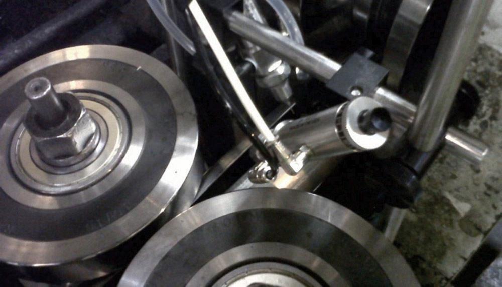
Figure 1
Installed on a mill near the weld box, a low-volume, low-pressure (LVLP) spray system can be set up to maximize flux
application efficiency.
Although stainless steels can have quite a few alloying elements, such as nickel, manganese, molybdenum, and silicon, the ability to resist corrosion is based on the presence of just one of them, chromium. Chromium combines with oxygen to form chromium oxide, which is the compound that prevents rust formation. The downside is that chromium oxide impedes bonding, especially when the alloy is subjected to very high temperatures such as those found in a tube or pipe mill’s weld box. Many tube and pipe producers that make 400 series products weld the seam as it is, without additives or fillers, and risk the problems associated with oxidation.
These producers have options. One is to enclose the weld box and blanket the weld area with argon gas. Because it’s inert, argon doesn’t remove the oxide coating, but it does help suppress oxidation in the weld box. However, given that it’s a dynamic situation, it is almost impossible to keep all of the oxygen out of the weld box.
A second way is to use a flux that dissolves and removes the original oxides, prevents reoxidation, and transfers weld heat to the seam.
Fluxes for the seam welding processes come in two forms, paste and liquid. Both have pros and cons, and the best choice depends on several factors.
A water-based brazing paste has the advantage of being easy to apply by brushing, rolling, or high-pressure spray gun, and it isn’t difficult to coat both sides of the coil before it is mounted onto the mill. This has three main disadvantages. First, the flux is applied manually in an offline operation, so it’s labor-intensive. Second, much of the flux coating flakes off before it reaches the weld box, reducing its effectiveness. Third, these flakes and particles end up in the accumulator and the rest of the mill, on the plant floor, and in the air. The debris is a nuisance and minimizing it requires relentless cleaning.
The liquid fluxes are water-based and available in two solids contents. They are sprayed on automatically, are clean, and do not pollute. When properly selected, installed, and aimed, the spray system applies the right amount of flux where it is needed, on both edge surfaces, as the strip feeds into the weld box.
Fluxes are essential when joining metals in ambient air, whether by soldering, brazing, or welding. When heated, fluxes perform four vital tasks:
It is important to distinguish brazing fluxes from welding fluxes. The difference is a matter of temperature. Brazing takes place between 850 and 2,200 degrees F; welding of ferrous metals takes place from about 2,600 to 3,000 degrees F. Tube and pipe mill weld boxes operate at approximately 2,600 to 2,800 degrees F, so a welding flux would seem appropriate for this application. However, the heat cycle used in tube and pipe production is too short to activate fluxes formulated for welding. Moreover, the fluoride content of these fluxes is low; high fluoride content is critical to tube and pipe welding applications.
In fact, various silver brazing flux formulations are suitable for this operation. These fluxes are active in the temperature range of 850 to 1,600 degrees F and have numerous industrial uses. The intense heat of the weld box activates the formulations and they remain active during the very short exposure time. The most common inorganic raw materials used in these fluxes are boric acid, potassium, sodium tetraborate, potassium fluoborate, and various fluorides.
Ferrous alloys, especially mild steel, are the most common materials for manufacturing tube and pipe. Among mild steels, typical surface oxides are iron oxides such as FeO and F2O3. Generally, iron oxides are either reduced at elevated temperatures or are displaced in the welding process.
A stark contrast is 409 stainless steel, which contains approximately 12 percent chromium. The chromium oxidizes to chromium oxide (Cr2O3), a tenacious and refractory oxide that tends to remain on the joining surface and interferes with the welding process. This is an even greater problem with 439 stainless steel, which contains approximately 18 percent chromium. The aluminum in alloys, such as 409 aluminized stainless steel, exacerbates the problem: Heating this material causes both aluminum oxide and chromium oxide to form. Aluminum oxide is also refractory and remains on the joining surface.
Using argon gas or another inert shielding gas affords some protection against high-temperature oxidation, but these gases don’t remove the original metal oxide tarnish, and they provide just partial protection in the dynamic environment of the weld box.
This is where fluxes perform their fundamental process function. At approximately 1,000 degrees F, the assemblage of inorganic chemicals is transformed into a glassy complex (at elevated temperatures, the forces that keep the molecules organized in a regular, repeated pattern break down and the molecules become disorganized, as they are in glass). Glass viscosity is important. It must be high enough to serve as a protective blanket, keeping oxygen diffusion to a minimum, while at the same time low enough to dissolve surface oxides effectively.
The primary means for oxide removal by alkali fluoborate fluxes is dissolution. Oxides are absorbed into the glass, leaving a very clean, deoxidized metal surface, which is properly prepared and protected for the welding stage.
Boron oxide (B2O3) is the glass former in the flux formulation. It provides the protective blanket for the base metals and the filler alloys, lowering the rate of oxygen diffusion to the metal surface so that it is below the rate of oxide removal from the joining surfaces. Potassium oxide (K2O) and sodium oxide (Na2O) are the glass modifiers, lowering the melting point and viscosity of the glass and improving flow.
Fluorides reduce the melting point and viscosity further, because they disrupt the cross-linkages in the borate glass structure. However, the improved fluxing action results mainly from the greater oxide dissolution capability of the glass because of its fluorine content. Fluorine is especially important because it aggressively attacks such oxides as Al2O3 and Cr2O3, accelerating their solution in the borate glass.
Silver brazing fluxes usually are used in conjunction with silver-based (BAg) alloys. The flux cleans and protects both the base metal and the filler alloy, allowing the filler alloy to flow and wet the base metal. This is not the case with the tube and pipe welding application because it uses no filler alloys or electrodes. Yet the outcome is the same. The flux removes oxides and protects the surface against reoxidation, yielding a strong, consistent weld seam. The simple addition of flux improves metallurgy, cosmetics, consistency, and stability of the welding process.
Learning about what flux does and how it does it isn’t enough. One important question remains: How does flux benefit a tube and pipe operation?
Finally, because flux use reduces tube rejects, it frees engineers and operators to spend more time on manufacturing and process improvements, and less time dealing with problems.
Spray systems have been used to assist in tube and pipe production for decades. Some systems are simple, such as one that sprays an antirust lubricant to the OD. Others are complex, such as a paint system triggered by a nondestructive testing unit to mark a bad weld.
A recently developed liquid flux is well-suited to an industrial spray system. Its viscosity is compatible with LVLP systems. Modern spray systems can hit a target area smaller than 0.13 in. and is adjustable to apply just the right amount of flux, somewhere between too little, which affects the weld quality, and too much, which wastes flux.
Mounting this sort of spray nozzle is a simple affair using an adjustable frame of ½-in. rod stock (see Figure 1). The best place to mount the spray valves is after the last set of rollers, but in some cases it is necessary to mount the spray system a few roller sets upstream. Trials have shown that an upstream location doesn’t affect the weld, but the spray can build up on the roller sets, necessitating an occasional cleaning.
Connecting the spray system’s on/off controller to the mill’s start/stop switch is an ideal way to start and stop the spray when needed. A flow monitor alerts the operator to an over- or underflow condition.
Because two valves operate at the same time, a single-valve operation channel can control the flow to each valve. Setup entails just two steps. First, the nozzle’s air supply is turned off and the drip rate adjusted for each of the valves to about 1 drop per second. Second, the air supply is turned on and the nozzles’ direction adjusted so they apply the spray to the strip’s edges.
Experiments using a variety of flux formulations and application methods showed that a liquid flux with a viscosity of 20 centipoise (cP) and LVLP technology produced the best results.


The Tube and Pipe Journal became the first magazine dedicated to serving the metal tube and pipe industry in 1990. Today, it remains the only North American publication devoted to this industry, and it has become the most trusted source of information for tube and pipe professionals.
start your free subscription
Easily access valuable industry resources now with full access to the digital edition of The Fabricator.

Easily access valuable industry resources now with full access to the digital edition of The Welder.

Easily access valuable industry resources now with full access to the digital edition of The Tube and Pipe Journal.

Easily access valuable industry resources now with full access to the digital edition of The Fabricator en Español.
In this episode of The Fabricator Podcast, Caleb Chamberlain, co-founder and CEO of OSH Cut, discusses his company’s...


