Lean times call for mean tactics—Part 1
A tube benders tools of the trade
 |
Personally witnessing the growth and maturing of the tube bending industry for the last five decades has been a great privilege, and as one of the remaining warhorses of this industry, I am in a position to take a long look back at this peculiar fraternity that we belong to. It doesn't seem all that long ago that to prove articulated ball mandrels could prevent thin-wall tubes from collapsing, I loaded a small rotary draw bender into a car trunk and set out across the western U.S. to demonstrate it.
Companies have come and gone over the years. I have seen many once-thriving, healthy companies with gifted artists who regularly pushed the boundaries of application feasibility falter and vanish. I have heard the clichés. "Tube bending is a black art" or "Tube bending is a lost art." It's true that tube bending is an art, but it's neither black nor lost. It's based on sound mechanical principles. I find it hard to believe that even today many basic nuances of proper tool positioning are misunderstood, if not misrepresented.
 |
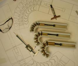
| Figure 1 A complete set of rotary draw bender tooling includes a bending die, wiper die, mandrel, pressure die, and clamp die. Some bends can be made successfully with just a bend die, pressure die, and clamp die. Difficult applications use a mandrel to prevent the tube from collapsing, a wiper die to prevent wrinkles, or both. |
Over the years I have often been asked what the single most important tool is for cost-effective precision tube bending. The answer is knowledge. Without doubt, the most important tool an operator has in his arsenal is between his ears. Its effectiveness is a matter of how he applies it to the task at hand. In these lean times in the tube fabricating arena (or, for that matter, manufacturing in general), it is imperative that we get the most cost-effective production from the equipment, the tooling, and the personnel involved not only for the most obvious reason, profitability, but—face it—for sheer survival.
Although many tube bending processes exist, this article addresses proper rotary draw bend tooling techniques with emphasis on ball mandrels and wiper dies. Rotary draw bending is by far the most versatile method of precision tube bending. But while it is more versatile, it is by necessity more complicated, involves more tooling (see Figure 1), and requires greater skill in setup and operation.
Regardless of the tube bending process used—whether it's press, compression, or rotary draw—the reaction of the workpiece to the bending force is similar. First, in all cases, the inner wall must compress, and the outer wall must stretch. Two other reactions are radial growth and material springback (see Figure 2).
 |
| Figure 2 Tube reacts to bending in four ways. The outer wall thins, the inner wall thickens, and the clamped section's radius grows. After the bending force is released, the tube springs back slightly. |
The extent of each of these can be approximated. When selecting a bend method, bear in mind that bending feasibility is determined in part by the material's ductility. The softer, or more ductile, the material is, the more it tends to collapse during the bending process, and therefore the more support it requires to hold its shape (ovality) in the bend area. While a harder material tends to flatten less, it does not tolerate as much support because it quickly reaches its elasticity limit and fractures.
Mandrels
First, let's look at mandrels. Common sense tells us that if we do not want a tube to collapse, we must fill it with something; this is a mandrel's function. In the early days of tube bending, this internal support consisted of sand, pitch, and even ice. Rudimentary cylindrical plug mandrels came next, and for many heavy-wall applications, these still are the most practical choice.
The most appropriate mandrel for the job is always determined by the application. The major determining factors include:
- Wall factor.
- D of bend.
- Type of tube material (and its yield strength, tensile strength, and percent of elongation).
- Weld seam location.
- Bending machine capacity, condition, and accessories (mandrel extractor, wiper bracket, follower-type or pressure-assisted pressure die, and so on).
- Production requirements.
- Part configuration (single-bend parts versus multiple-bend parts).
- Tolerances of raw material (consistency).
- Prebend operations (weldments, holes, beaded ends, fittings).
- Final part usage.
- Final part tolerances and inspection criteria (ovality, wall thinning).
- Restrictions on lubrication (including postbending lubricant removal).
To understand mandrel selection, we must step out of the real world and assume we have no variables such as machine inconsistency or part slippage in the clamps; we must also assume that we have pristine tooling.
It cannot be stressed enough that for the best results, use only the minimum amount of support. The reason for this is obvious—as the workpiece support increases, so does the drag (friction between the mandrel and the tube). When working with softer materials, this translates into more material stretch and outer wall thinning. On less ductile materials, it causes tube breakage.
 |
| Figure 3 The D of bend is calculated by dividing the centerline radius (CLR) by the tube's OD. |
Mandrel Material. The first consideration is to match the mandrel material to the tube material. Generally, go with the toughest tool material possible for the most longevity. Be careful not to select a material that is too brittle. There is nothing quite like the experience of ordering tooling made from an unusual material; paying a premium price for it; waiting longer than usual for it to come in; setting it up to make a tight bend on expensive, thin-wall ducting material you waited for months to be delivered and watching the tooling shatter on the first bend.
The most common tooling material combination is industrial hard chroming over hardened tool steel. This combination includes -06 material for small ODs to S-7 material for larger sizes. Other common combinations are coatings such as titanium nitride or titanium carbide over fully hardened D-2 tool steel. It should be noted, however, that these material/coating combinations do not work well with materials such as titanium, MONEL® alloys, INCONEL® alloys, and stainless steel. Generally, these tube materials work best with aluminum-bronze mandrels in varying degrees of hardness determined by the severity of the application. Various types and grades of machinable plastics are becoming more common also.
 |
| Figure 4 Tooling selection is based on the tube's wall factor (listed in the left-hand column, 10 through 200), the D of bend (listed across the top row, 1D through 3.5D), and material type (ferrous or nonferrous). Click here for a PDF version of the Tool Selection Guide |
A qualifying factor is needed to establish the severity of a given application; the severity determines the amount of support the tube requires. First, calculate the wall factor of the tube by dividing the OD by the wall thickness. Then figure the D of bend by dividing the centerline radius (CLR) of the part by the OD (see Figure 3). Comparing the wall factor to the D of bend gives some guidance as to the number of mandrel balls needed (if any) and the optimal pitch (see Figure 4).
The amount of support required increases as the wall factor increases and D of bend decreases.
These are just guidelines. Less ductile materials generally require fewer balls, whereas more ductile materials require more balls. Do not forget, however, that more support leads to more drag.
Mandrel Pitch. Some criteria regarding mandrel pitch selection should be explained. Mandrel pitch (ball centerline to ball centerline) is determined by the size of the linkage in the mandrel.
The linkage allows the mandrel to articulate or flex. Most universal flexing linkages are the ball-and-socket type, so they can operate in three dimensions. Two main points govern linkages:
- The smaller the link, the tighter the mandrel pitch.
- The smaller the link, the less strength it has.
As shown in Figure 4, the most severe applications (large OD and thin wall or tight CLR) require close-pitch mandrels. Very extreme cases require ultraclose-pitch mandrels (ultraclose-pitch mandrels are two link sizes smaller than the standard mandrel for a given tube OD). As the pitch of the mandrel decreases, so does the overall length of the ball string. In some cases, additional balls must be added to the mandrel to compensate for this. However, additional balls mean additional drag. Drag must be reduced in other areas of the tooling setup if the material cannot withstand the additional drag.
To put it simply, use the least amount of support possible.
Mandrel Fit. Another aspect of mandrel design is how well it fits inside the tube. Regardless of the amount of clearance between the mandrel diameter and the tube ID, one factor is universal: The mandrel shank diameter is always larger than the mandrel ball diameter. For typical job shop work, the total clearance between mandrel shank diameter to the tube ID is 25 percent of the tube's wall thickness. Note that this is total clearance, not clearance per side. After using this percentage to establish the shank diameter, subtract 0.005 in. to determine the ball diameter.
| Suggested Mandrel Location to Tangent | |||||||||
|---|---|---|---|---|---|---|---|---|---|
| Standard Pitch |
Tube OD | 1⁄4 – 5⁄16 | 3⁄8 – 7⁄16 | 1⁄2 – 11⁄16 | 5⁄8 – 11⁄16 | 3⁄4 – 7⁄8 | 1 | 11⁄8 – 13⁄8 | |
| Tangent | 1⁄16 | 1⁄8 | 1⁄8 | 5⁄32 | 5⁄32 | 3⁄16 | 3⁄16 | ||
| Tube OD | 11⁄2 – 15⁄8 | 13⁄4 – 2 | 21⁄8 – 21⁄2 | 25⁄8 – 31⁄4 | 33⁄8 – 41⁄2 | 45⁄8 – 51⁄4 | 53⁄8 – 6 | ||
| Tangent | 7⁄32 | 7⁄32 | 1⁄4 | 5⁄16 | 11⁄32 | 3⁄8 | 7⁄16 | ||
| Close Pitch |
Tube OD | 11⁄4 | 11⁄2 – 15⁄8 | 13⁄4 – 2 | 21⁄8 – 21⁄2 | 25⁄8 – 31⁄4 | 35⁄8 – 41⁄2 | 45⁄8 – 51⁄4 | 53⁄8 – 6 |
| Tangent | 1⁄16 | 1⁄8 | 5⁄32 | 5⁄32 | 3⁄16 | 3⁄16 | 1⁄4 | 1⁄4 | |
| Figure 5 The mandrel location is affected by clearance, CLR, the tubing material, and other factors. Use the tube OD as a guideline to find the approximate mandrel location, then make several test bends until the bend is satisfactory. | |||||||||
Some applications require a tighter fit. For example, aerospace applications typically use 10 to 15 percent of the wall thickness for the shank OD and reduce this by 0.003 in. to determine the ball diameter. Some extreme applications, such as large-diameter/thin-wall aircraft ducting, have severe specifications such as zero (0.000-in.) clearance on the shank of the mandrel and possibly 0.001 to 0.002 in. of drop for the balls. Compensating for the drag under these conditions is a masterful trick when accomplished successfully by a bending artist, and likely results in tube slippage and breakage when performed unsuccessfully by a bending novice.
Mandrel Placement. Now let's look at proper placement of the mandrel in the tool setup. Let me begin by saying that no hard and fast rules exist for proper mandrel placement. I cannot stress this enough. When it comes to settings, positioning, pressures, speeds, clearances, and other aspects of tooling setup, the most experienced teacher imparts his best advice as just that: advice. Mandrel placement instructions are merely recommended guidelines. No one-size-fits-all solution exists for mandrel placement.
One thing is certain, however: The mandrel shank is located slightly past the tangent point with the balls in the clamping area. This puts the greatest load on the shank, not on the linkage. (Incidentally, this also is why the shank diameter is slightly larger than the ball diameter.) Published guidelines (see Figure 5) can help get the mandrel close to its optimal location. It's up to the bending machine operator to make a few test bends and adjust the mandrel placement to optimize the bend. After getting the best possible bend, log it to knowledge.
 |
| Figure 6 A wiper die is used to prevent wrinkles from inner wall compression on the inside radius during the bending process. |
Wiper Dies
The function of wiper dies is to further control and contain the tube on the inside of the bend radius while forming (see Figure 6). They generally are used in conjunction with ball mandrels. A mandrel alone cannot control the inherent wall compression at the inside of the bend. Without a wiper die, compression causes the tube wall at the inside of the bend to wrinkle. Wiper dies can be the most frustrating tool in the setup for many reasons.
Wiper Die Tips. If machined properly, the tip thickness generally is between 0.005 and 0.007 in. This thickness varies with the size of the wiper. This tool, like the mandrel, is in a state of constant friction with the workpiece. The friction and the pressure exerted by the workpiece (pressure that originates from the pressure die) mean that the thin tip is under severe conditions during bending. Forgetting to lubricate the wiper can mean failure on the first test bend.
Wiper die material selection is similar to that of mandrel material selection. However, because wiper die tips are so thin, making a wiper die from a harder material doesn't extend the tool's life effectively. In fact, using a harder material increases the likelihood of tip breakage.
Most wipers that are machined from steel rarely are harder than 32 Rockwell C. With the increasing popularity of wiper die tips that do not have to be reworked or sharpened, bending shops can maintain an inventory of these items. Made to be a disposable commodity tool, they are used until they cannot perform their intended function properly and discarded. Time and money are not lost sending them back to the manufacturer for refurbishment. However, disposable tips have limitations.
Because most of these tips are machined from heavy-wall tube stock, parted in half after the ID and OD are turned, the resulting tube groove depth has a feature called negative lip. This refers to tube groove depth that is less than 50 percent of the tube diameter. Negative lip can be detrimental in thin-wall applications, especially in tight-radius bends.
One of the other drawbacks of tips is that they are much more difficult to incorporate on machines equipped with an automatic wiper lubrication system. To get around this, you might consider feeding the lube port to the wiper tip holder instead of the wiper.
Disposable tips are well-suited to high-volume production runs, especially if the workpieces are from 0.750 to 3.00 in. OD.
Wiper Die Failure. Probably the most frequent cause of premature wiper failure is improper or inadequate lubrication, followed by improper setup. Regarding lubrication, the tube material must be matched to the lubricant used. This is as critical as incorporating the proper tooling materials with the tubing, for optimal tool longevity and to prevent tube slippage, wall thin-out, and even tube fracture.
Setup. The pitfalls in setup are tool rigidity, rake angle, and placement. An incorrect setup can cause premature wiper die failure.
Rigidity. If the setup is not rigid enough—that is, if the setup allows the wiper to move during the bending cycle—expect to get only a fraction of the wiper's effective work life, if any. The wiper must be rigid.
Rake angle. A proper rake angle allows the wiper's tube groove to contact the tube only at the tip. The back end of the wiper does not touch the tube.
If the wiper is set up parallel to the tube (as is the pressure die on the other side), the two act as a secondary set of clamps and will cause the tube to be pulled apart, or at least cause the tube to slip and wrinkle.
Placement. Proper placement is a matter of determining the proper distance from the wiper tip to the point of tangency. The tip is only 0.005 to 0.007 in. thick, so theoretically, if you were to set the tip of the wiper at the tangent, the tube would have a step in it. Also, the wiper tip would get pulled off.
Setup Guidelines. The tip should be behind (not at, and never beyond) tangent. It should be set with the proper height at the front as well as the back to run parallel to the bend die when the bend die rotates. The transition from the bend die grip area to the wiper should be smooth, with little or no step to the touch.
The most severe applications are those with high wall factors and smaller D of bend. Any adjustment in wiper rake angle generally must be compensated with a corresponding adjustment to increase or decrease the pressure die force. It is always best to run the most rake you can get away with to reduce the stress on the wiper tip.
Finally, yet important, if you find that over time you seem to get less and less production from wipers between reworking or replacing them, the bend die could be the cause. Bear in mind that the only support that the wiper tip has is the contour of the bend die tube groove just behind tangent.
Coincidentally, the bend die typically shows the greatest amount of wear in this area. When the bend starts, the pressure exerted on the wiper tip causes it to conform to the bend die's shape in that area. If the bend die is worn and oversized, do not expect much life from your wipers.
A final thought with regard to the wiper die mounting on your machine. Some machines have wiper brackets (holders) that are inadequate to accommodate a wide CLR range. These brackets can lack rigidity, which is especially crucial in benders that have stacked tooling. If you have bend quality inconsistency or if the wiper die life depends on the wiper's location in the tool stack, you probably need to beef up the bracket.
It should also be noted that on stacked tool setups—especially where different bend die radii are used— wiper brackets must get very elaborate to allow each wiper to have independent adjustment. This is especially important (and hard to accomplish) with regard to rake angle adjustments.
The Most Important Tool Is Knowledge
The best tooling and state-of-the-art equipment will not operate properly or profitably unless you engage the most important tool first.
Tube bending by nature is a continuous overlay of variables. A true artist eliminates the variables he can and manipulates those that remain. Consistent procedures do not always guarantee consistent results, but they are absolutely the best insurance a bending artist has. In addition, it is the best way to learn.
Ronald Stange is the owner and founder of Tools for Bending Inc., 194 W. Dakota Ave., Denver, CO 80223, 303-777-7170, fax 303-777-4749, tfb@toolsforbending.com, www.toolsforbending.com.
About the Author
About the Publication

subscribe now

The Tube and Pipe Journal became the first magazine dedicated to serving the metal tube and pipe industry in 1990. Today, it remains the only North American publication devoted to this industry, and it has become the most trusted source of information for tube and pipe professionals.
start your free subscription- Stay connected from anywhere

Easily access valuable industry resources now with full access to the digital edition of The Fabricator.

Easily access valuable industry resources now with full access to the digital edition of The Welder.

Easily access valuable industry resources now with full access to the digital edition of The Tube and Pipe Journal.

Easily access valuable industry resources now with full access to the digital edition of The Fabricator en Español.
- Podcasting

In this podcast episode, Brian Steel, CEO of Cadrex Manufacturing, discusses the challenges of acquiring, merging, and integrating...
- Trending Articles
1
Fabricator achieves extraordinary with simple approach

2
Team Industries names director of advanced technology and manufacturing

3
New trails, old-school values for Precision Tube Laser

4
Orbital tube welding webinar to be held April 23

5
Blades designed for cutting medium metals