


Selecting the right mandrel and wiper
Optimizing the combination for cost-effective tube bending
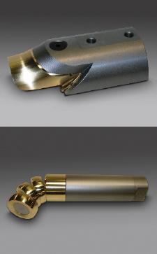
Figure 1 Introduced in the mid-1980s, inserted (or standard) tooling can withstand the pressure associated with many bending applications. Replacing the insert, the bronze-colored portion at left, is less expensive than replacing the entire tool.
Whether the times are lean or fat, cost-effective tube bending always makes sense. Just like any other manufacturing operation, keeping rotary draw tube bending profitable demands process control, which has three aspects: (1) Bringing under control all of the elements of the bending process to eliminate unpredictable results, (2) optimizing these elements for increased productivity within the bounds of quality requirements, and (3) translating this efficiency into profits.
Rotary draw tube bending is a tool-intensive metal forming operation. The mandrel and wiper (see Figure 1) are critical to supporting the tube at the point of bend to produce consistent, high-quality results. The objective of this support is to deform the tube plastically along the arc of the bend with minimal distortion of its cross section. Therefore, the mandrel and wiper are primary elements in the rotary draw tube bending operation.
The Mandrel-Wiper Chart
For many years tube bending engineers have relied on tables to specify the mandrel and wiper needed for a job. Many use a mandrel-wiper chart (see Figure 2), which is a convenient way to convey information derived from mathematical formulas and rules of thumb.
The typical mandrel-wiper chart displays the recommendations by wall factor versus D of bend. The wall factor is the tube or pipe"s OD divided by the wall thickness. The D of bend is the centerline radius of the bend divided by the tube or pipe"s OD. Where these two measures intersect on the chart is the recommendation for the mandrel and wiper.
On most mandrel-wiper charts, this recommendation has three components: (1) Whether a mandrel is required for the tube bend; (2) if so, the pitch and number of balls; and (3) whether a wiper is required. Some charts supply additional information, such as whether standard tooling or high-pressure tooling is needed to make the tube bend.
For example, for a 2-inch OD, 0.065-in. wall thickness, and 4-in. centerline bending radius:
Wall factor = 2 in. / 0.065 in. = 30.8
D of bend = 4 in. CLR / 2 in. OD = 2.0
Using the mandrel-wiper chart in Figure 2, find the row with the largest wall factor equal to or less than 30.8. This is row 30. Similarly, find the column with the largest D of bend equal to or less than 2.0. This is column 2. At this intersection, the value is R2W, which indicates a regular-pitch, two-ball mandrel with wiper.
The W has a further meaning: Standard tooling, as opposed to high-pressure tooling, is sufficient to make the tube bend. An H in place of the W would indicate that high-pressure tooling should be used.
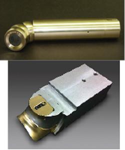
Figure 3 Unlike standard inserted tooling, noninserted tooling has continuous working surfaces. This type can withstand higher pressures than inserted tooling.
Zones of Difficulty
The mandrel-wiper chart in Figure 2 indicates that the greater the wall factor, the more difficult the bend. Conversely, the greater the D of bend, the less difficult it is. Therefore, the most difficult bends are at the lower left-hand corner of the chart, and the least difficult bends are at the upper right-hand corner. Accordingly, the tooling recommendations sort themselves into four zones of difficulty (see Figure 2).
The first zone, emanating from the upper right-hand corner, includes those bends that do not require a mandrel or wiper. This is because either the wall thickness relative to the tube diameter is heavy enough or the centerline radius relative to the tube diameter is large enough so that the tubing has sufficient strength to support itself at the point of bend.
The second zone consists of bends that require a standard mandrel but no wiper; the third zone requires a standard mandrel and a standard wiper. Finally, the fourth zone, in the lower left-hand portion of the table, includes the bends that are the most difficult because of very thin walls or very tight bend radiuses. These bends require both a high-pressure mandrel and a high-pressure wiper for full control of the tubing at the point of bend.
Since the advent of mandrel and wiper tooling with replaceable inserts a quarter-century ago (see Figure 1), it has become important to distinguish which tube bends are best-suited to their use and which ones require their noninserted counterparts (see Figure 3). This divide between inserted (or standard) tooling and noninserted (or high-pressure) tooling is critical when the extremes of thin walls and tight bend radiuses require relatively high radial pressure from the pressure die against close-fitting mandrels and wipers set at zero rake. When using standard tooling, substantial radial pressure can affect the tube with marking, distortion, and excessive drag from the parting lines; it also can damage the working surfaces of the tooling.
To summarize, the second and third zones call for standard mandrels and wipers for the most cost-effective tooling to make these bends, and the fourth zone calls for high-pressure mandrels and wipers. Some old mandrel-wiper charts don"t make the distinction between standard and high-pressure tooling. For example, if an obsolete chart indicates a close-pitch, five-ball mandrel [or above], this should be interpreted as advice to use high-pressure tooling.
Adjusting for Secondary Parameters
Although the wall factor and the D of bend are the primary parameters in selecting the right mandrel and wiper for a tube bending job, other important factors come into play, such as the degree of bend and the tube material. However, the two-axis nature of a mandrel-wiper chart does not allow for a direct input of these secondary parameters. Instead, they must be given careful consideration and accounted for by making adjustments.
Bending difficulty increases as the bend angle, or degree of bend, increases. Because degree of bend is a secondary parameter, most mandrel-wiper charts are compiled from information concerning a 180-degree bend. If the degree of bend is less than 45 degrees, adjust one column to the right (the next higher D).
You can make similar adjustments for tube material. Mandrel-wiper charts are based on mild steel tubing or a material with similar elasticity and plasticity. This includes all nonstainless steels and most nonferrous metals. However, some materials are more difficult to bend and require firmer control at the point of bend. To account for this, you should adjust the recommendation one column to the left for stainless steel, titanium, copper-nickel, and T6 aluminum. Adjust two columns to the right for high-nickel stainless steel (314 and 329 grades) and nickel alloy such as INCONEL® alloy.
Chart Limitations
All mandrel-wiper charts are limited by the practical range of rotary draw tube bending. That said, the chart in Figure 2 is quite broad. First, it spans a wall factor of zero (solid rod) to 200 (for example, a 2-in.-OD tube with 0.010 WT), which is rare. Second, the D of bend ranges from 3/4, which is the tightest tube bend suitable for rotary draw tube bending (and then only in limited cases), to 12, which is seldom encountered because roll and press bending usually are more efficient for such loose bend radiuses.
Another important limitation to bear in mind is that mandrel-wiper charts are compiled for round tube. Still, it is possible to approximate the mandrel and wiper tooling needed for square, rectangular, oval, and elliptical tube from a chart like that in Figure 2. Generally, they should be treated like the tougher materials by adjusting one column to the left. However, there is no rule of thumb because the ratio of the major to minor axis of nonround tubing, the corner radius, and the plane of bend (whether the bend is hard way or easy way) all must be factored into that adjustment.
Finally, all mandrel-wiper charts are limited by assumptions about the tooling and its setup. For example, the chart in Figure 2 assumes the operator is using certain best practices, such as the "forward nose" setup of a link-type mandrel, as opposed to a cable mandrel, which is often set with the first ball at the line of tangency. It also assumes certain specifications, such as a precision nose radius for the mandrel instead of a larger high-production one and a nose diameter that is close-fitting (Nose diameter = OD - WT x 2.21) rather than loose.
Affordable Tooling
This objective method of using a mandrel wiper chart to select the right mandrel and wiper for a tube bending job opens the way to cost-effectiveness:
1. It specifies which tooling is sufficient to achieve process control. The job is not undertooled and so is not unstable and unpredictable. Nor is the job overtooled so that more tooling is consumed per bend than is necessary.
2. A job under process control reduces the incidence of failure. Failure, often from unbalanced forces being applied to the tube, tooling, or the machine, is expensive. It disrupts the flow of work. It scraps tubing. It shortens tool and machine life.
3. Finally, process control increases productivity. Fewer resources are needed in terms of labor, machine time, tooling and supplies, and overhead to get the job done.
About the Author
About the Publication
subscribe now

The Tube and Pipe Journal became the first magazine dedicated to serving the metal tube and pipe industry in 1990. Today, it remains the only North American publication devoted to this industry, and it has become the most trusted source of information for tube and pipe professionals.
start your free subscription- Stay connected from anywhere

Easily access valuable industry resources now with full access to the digital edition of The Fabricator.

Easily access valuable industry resources now with full access to the digital edition of The Welder.

Easily access valuable industry resources now with full access to the digital edition of The Tube and Pipe Journal.

Easily access valuable industry resources now with full access to the digital edition of The Fabricator en Español.
- Podcasting

In this episode of The Fabricator Podcast, Caleb Chamberlain, co-founder and CEO of OSH Cut, discusses his company’s...
- Trending Articles
1
Zekelman Industries to invest $120 million in Arkansas expansion

2
3D laser tube cutting system available in 3, 4, or 5 kW

3
Corrosion-inhibiting coating can be peeled off after use

4
Brushless copper tubing cutter adjusts to ODs up to 2-1/8 in.

5
HGG Profiling Equipment names area sales manager
