Editor-in-Chief
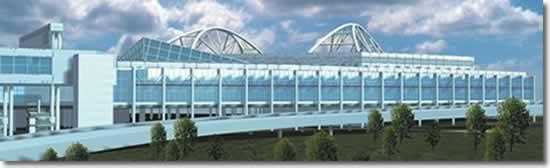 |
| Texans will remind you that things are bigger in Texas, and the Dallas Convention Center is just another example, as this computer drawing shows. Two 860-ton roof truss assemblies, fabricated from large-diameter pipe, make it possible for Dallas to boast that it currently has the largest column-free, single-structure exhibit hall in the U.S. |
The same phraseology can be applied to convention centers, as these facilities have gone beyond just housing tradeshows and now play host to entertainment and sporting events. In all those cases, no one wants to be stuck behind a support column.
Realizing this, Dallas governmental representatives spent time in 1998 touring convention centers. The civic leaders used the trips as opportunities to gain inspiration and guidance as they planned for a grand expansion of the Dallas Convention Center.
The final decision: Dallas needed a convention center design that created a large exhibition space free of columns, while at the same time unified existing buildings with the new design.
Nearly five years later, two 382-foot-long and 60-ft.-wide roof trusses, fabricated from giant spans of heavy-duty pipe, have made the vision a reality. The 860-ton assemblies now hold up the roof of what Dallas city officials call the largest column-free, single-structure exhibit hall in the U.S.
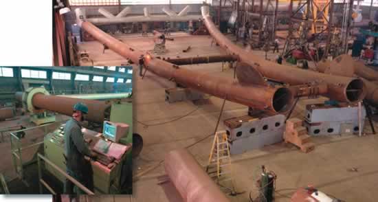 |
| To achieve the parabolic shape of the roof truss arches, the pipe fabricator relied on induction bending and internally developed computerized tooling. Bend radii of the arch segments were between 297 ft. 10 in. and 467 ft. 3 in. |
From a structural standpoint, designing a 200,000-square-ft. building without the benefit of columns is challenging, to say the least. Datum Engineers Inc., the structural engineering firm hired for the remodeling and expansion of the 46-year-old convention center, also had to figure out how the facility would be supported over five active railroad tracks and a rail line for Dallas' rapid transit system.
Structural designs initially centered on cable supports. Some designs revolved around a center support with cables connected to the edges, and others called for columns on the side with cables supporting the roof from that position.
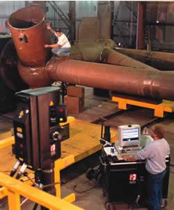 |
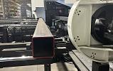
| A laser coordinate measuring machine was used to measure the pipe assemblies. The information was then fed into the CAD software to ensure proper connection. |
In the end, the designs wouldn't work. Lack of real estate was a problem. "We couldn't cable-stay a roof because we didn't have any place to back-tie to," said Michael Whitney, a project manager and design engineer on the project and now principal with Structural Engenuity Inc. Either the railroad tracks were in the way, or any open space that might have been usable was not because the ground was earmarked for future convention center expansion.
As the design evolved, the idea of fabricating roof truss assemblies from pipe emerged.
"The advent of using glass as canopies or grooves and things like that has led to more use of pipe [in building design]. You start getting into a lot of space frame kind of structures," said J. Warren, an architect with HKS Inc. and project director for the Dallas Convention Center expansion. "Pipe, obviously, is the most efficient to get something to work."
With pipe now on the board as a structural alternative to cables, the design team thought of a bridge design that had gained a bit of fame in the late 1990s for its supports made of pipe. The Damen Avenue bridge in Chicago features 48-in.-diameter steel pipe fabricated to make tubular supports, which measure 243 ft. in length.
BendTec Inc. of Duluth, Minn., built the bridge supports and, consequently, built a reputation for its ability to fabricate large pipe supports for structural applications. That experience led to its involvement with the Dallas Convention Center project.
The final design called for two truss assemblies to support a roof that would cover a 4.5-acre exhibit area. The trusses would mimic the shape of the supports in the Damen Avenue bridge.
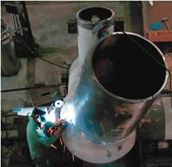 |
| All connections of primary members of the roof truss assemblies were made with complete-penetration groove welds made using flux-core arc welding and submerged arc welding. |
"Arches aren't really new," said Robert Meierhoff, BendTec's president and CEO, "but the ability to form them [from large-diameter pipe] is getting more attention.
"These trusses are parabolic shapes, so it takes a little bit more specialized equipment to come up with the curve that is necessary."
BendTec relied on heat induction to bend the long and heavy lengths of pipe. For the Dallas Convention Center project, the material used for the four arches was 48-in.-OD pipe per standard API 5L Gr. X52, an American Petroleum Institute standard. Wall thickness of the pipe varied from 0.625 in. to 1.5 in.
With induction bending, large-diameter pipes, such as the ones used in the roof truss assemblies, have an induction coil placed around a small circumferential section. The coil heats the pipe to a very high temperature, usually between 800 and 2,200 degrees F depending on the material type. When the bending temperature is reached, the pipe passes through the induction coil, and the bending force is applied.
Fabricators typically work with smaller-sized pipes and longer radii. As a result, they often form tubes by rolling them cold, rather than relying on the generally more expensive method of heat induction pipe bending.
For the Dallas Convention Center, BendTec used induction bending to shape the approximately 30-ft.-long arch segments to achieve the parabolic shape. Computerized tooling, developed by BendTec specifically for long-radius bending, was used to bend the arch segments. Bend radii of the arch segments were between 297 ft. 10 in. and 467 ft. 3 in.
BendTec fabricated the rest of the roof truss assemblies as well:
All connections of primary members of the roof truss assemblies were made with complete-penetration groove welds made using flux-core arc welding (FCAW) and submerged arc welding (SAW).
For the complex connections at the truss level, where four to six chords or members might come together, 5-ft.-diameter spheres were used. The spheres were constructed from 60-in.-OD hemispherical heads formed from A572 Gr. 50 plate, and the head thickness varied from 2 to 3 in. The heads were welded together using the SAW process.
"We are probably more of a pipe fabricator in general rather than strictly a structural type of fabricator," Meierhoff said. "So in some of the various projects where we have connected or made manifolds with three or four lines coming together, we have used spheres. I guess it dates back to the Tinker Toy® idea."
"Probably the most challenging part of the project was putting it together and making sure that everything fit. For something as large as this, you certainly don't want something not to fit when it's being installed," Meierhoff added.
The horizontal cross-brace connections between the trusses were of special interest. Because the arches were slanted toward the center of the truss assembly, they proved to be some of the most critical parts in ensuring proper fit-up.
Computer-aided design (CAD) software helped. By accurately drawing the entire truss assembly on CAD, engineers could isolate the connections and determine patterns for getting the cross braces to intersect the arch.
A laser coordinate measuring machine was used to measure the pipe assemblies. The information was then fed into the CAD software to determine if any discrepancies existed between real-world and virtual-world measurements.
In one last check, BendTec prefitted the nine shop-fabricated segments that made up each arch before they were to be shipped out. By this time the roof truss assembly pieces ranged in length from 30 to 58 ft.
Meierhoff said 70 truckloads were needed to get all the necessary pieces to Dallas for final assembly. Because of the size and weight restrictions for shipping, each end truss was split horizontally and delivered in two pieces.
The roof truss segments were assembled in the field below the very spaces that were to be their final resting places.
When finally put together, the roof truss assemblies were placed on hydraulic jacks and slowly lifted onto concrete columns. The north end truss assembly sat on two columns, one at each end. The south end truss assembly sat on one column positioned at its center.
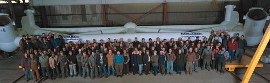 |
| BendTec employees proudly stand beside their work. In this case, it's a piece of a roof truss assembly for the Dallas Convention Center. |
The column arrangement was simply a reflection of the space allotted between the train tracks, Whitney said. In addition, any further expansion will require exhibit halls to mimic the same one-column approach for roof truss assembly support.
In September 2002 the facility welcomed the Texas Association of School Administrators/School Boards and its 11,000 members. Since then thousands have walked the column-free exhibit hall, which as of early 2003 was still the world's largest single-structure facility of its kind.
In the end, the citizens of Dallas may have gotten more than a new addition to its refurbished convention center.
The roof truss assemblies "not only hold the ceiling up, they have become an icon for the city," said Greg Elam, senior vice president of communication for the Dallas Convention & Visitors Bureau.
Computer-generated drawing courtesy of the Dallas Convention & Visitors Bureau.
Photos courtesy of BendTec Inc.
BendTec Inc., 366 Garfield Ave., Duluth, MN 55801, 218-722-0205, fax 218-722-6598, www.bendtec.com.
Dallas Convention & Visitors Bureau, 325 N. St. Paul St., Suite 700, Dallas, TX 75201, 214-571-1000, fax 214-571-1008, www.visitdallas.com.
Datum Engineers Inc., 6516 Forest Park Road, Dallas, TX 75235, 214-358-0174, fax 214-358-0445, www.datumengineers.com.


The Tube and Pipe Journal became the first magazine dedicated to serving the metal tube and pipe industry in 1990. Today, it remains the only North American publication devoted to this industry, and it has become the most trusted source of information for tube and pipe professionals.
start your free subscription
Easily access valuable industry resources now with full access to the digital edition of The Fabricator.

Easily access valuable industry resources now with full access to the digital edition of The Welder.

Easily access valuable industry resources now with full access to the digital edition of The Tube and Pipe Journal.

Easily access valuable industry resources now with full access to the digital edition of The Fabricator en Español.
In this episode of The Fabricator Podcast, Caleb Chamberlain, co-founder and CEO of OSH Cut, discusses his company’s...