


Director of Product and Business Development
A great deal of progress has been made in recent years to advance the art of cold bending, but this doesn’t mean that it has become easy. Some fabricators say, “If the material can be made to flow under stress, you can bend it,” but most people involved in the bending industry know that it’s not quite that simple. Of course, a bending application requires the correct bending tools, the right machine, and a knowledgeable operator, but the physical design of the part also is extremely important. It determines the equipment and tooling necessary to bend the part.
Many designers are familiar with the cost savings and production advantages that tube bending affords the manufacturing department; however, many are unfamiliar with the proper procedures to follow when designing parts for bending. Good part design contributes to production efficiency by shortening loading and unloading times and thereby reducing cycle times. It also lowers manufacturing costs by reducing the machinery investment and, in some cases, eliminating some of the wear tools.
When designing a part for bending, four factors contribute to choosing the proper equipment and tooling for the job:
In most cases, the material required for a bent part is a function of its intended use. When designing the part for bending, the material’s ductility—its ability to elongate—can be a critical factor. Greater ductility correlates to easier bending and a greater likelihood of a successful bend.
When cold bending, sufficient material elongation is required to achieve the desired angle and centerline radius (CLR) without fracturing. A guideline for calculating the material’s elongation requirement, which is measured in percent, takes the tube’s outside diameter (OD) and the CLR into consideration:Elongation Required = [(OD/2)/CLR] x 100
For example, when bending a 2-in.-OD tube on a 4-in. CLR, the material elongation must be at least 25 percent.
This guideline can help produce a successful, high-quality bend using basic bending machine controls and features. If the bend is outside these parameters, the tube may be bent successfully, but it might need additional assistance in the form of pressure die assist, material boost, or material heating. These options and features require an additional equipment investment and more operator training, and they might lead to slower production rates.
A related factor is the bend severity, also known as the D of bend, which also is based on the CLR and the OD:
D = CLR/OD
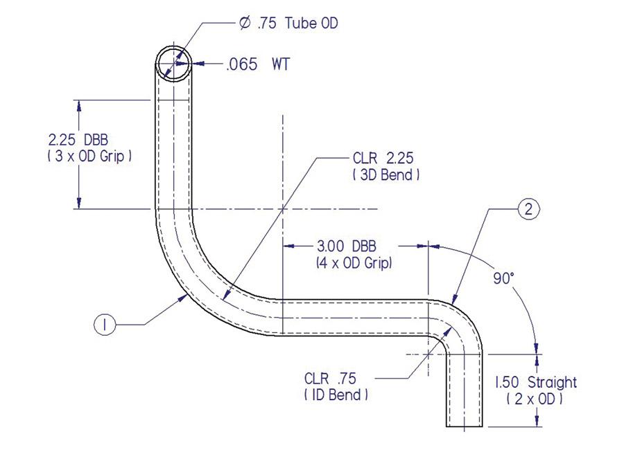
Figure 1
Increasing the D of bend increases the likelihood of a successful bend. Because D=CLR/OD,
the D of bend increases when the part is redesigned to have a larger CLR or a smaller OD.
As the D of bend decreases, the likelihood of a failure or tube deformation increases (see Figure 1). Designers can use two material selection strategies to improve the likelihood of success when working with a low D of bend (less than 3):
The number of bends per part and bend radii also play a significant role in determining the equipment necessary to complete the job. The main concern is whether the bender should be equipped with numerical control (NC) or computer numerical control (CNC). The former is tube manipulation by manual control, while the latter is manipulation and carriage motion by machine control.
As would be expected, a one-bend part is the easiest to form and usually requires the least in terms of machine options, tooling, and equipment. As bends are added to the part, the complexity increases, and it typically requires more bending machine options and capabilities. For a multibend part, a CNC bender typically is more effective than an NC bender.
A CNC tube bender uses a carriage to advance and rotate the tube for each bend. An NC bender doesn’t have this capability, so the operator must position the tube for each bend. Mechanical
fixtures help ensure the operator positions the tube correctly, but as the part volume or part complexity increases, the viability of the NC option decreases because the cost of fixturing increases, as do the setup time and cycle time. If a project calls for a variety of multibend parts, the CNC option becomes even more cost-effective because CNC programming is fast and bending is accurate without fixturing.
For bending parts that have bends with more than one radius, a multistack machine is necessary to complete the part without changing the machine and tooling setup. Many fabricators use multistack benders, but they represent a larger equipment and tooling investment than single-tool benders because every radius change requires an additional tool set.
Since the machine or operator must reposition the tube into a different die set for each bend, the production rate decreases with each radius change required. In general, a multibend, multiradius part will require an additional investment to produce, compared to a multibend, single-radius part.
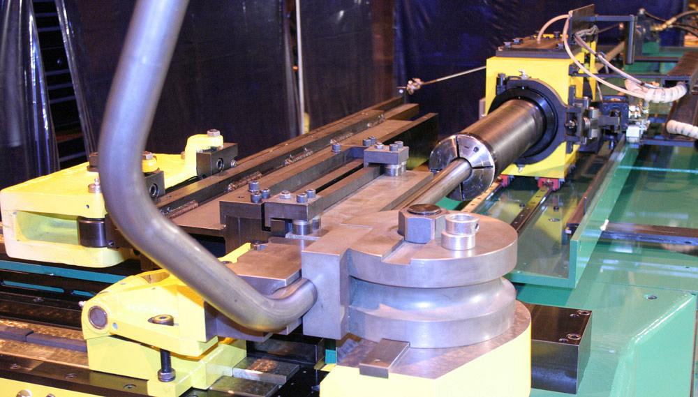
Another critical factor is the distance between bends (DBB), which is the amount of straight material between bends available for gripping. Increasing the grip length decreases the likelihood of the tube slipping during the bending process. It also allows bending with lower pressures and forces applied by the machine, prolonging machine life and wear item replacement.
As the bends become more severe (as the D of bend decreases), the bending tension increases, as does the required DBB. The minimum clamping length for basic tube bending machines is as follows:
If the bend doesn’t fall within these parameters, options are available. However, most of these result in sacrificing quality, such as part marking from aggressive tooling grip surfaces, or investing in additional features, such as push bending or a multistack bender with compound tooling for gripping.
As the bending severity increases—a thinner wall, a less ductile material, or a smaller D of bend—so do the tooling requirements. In most cases a mandrel and wiper die are not required if the tubing has sufficient WT and D of bend. Bending machine and tooling manufacturers can supply charts that specify conditions in which a wiper die and mandrel are required.
Maximizing the D of bend, increasing the WT, or changing to a more ductile material (or all three) decreases the tooling investment, for example by eliminating the need for mandrels and wiper dies. These are wear items that need regular replacement and can be damaged by improper setup. In some cases careful bend planning can reduce or eliminate the need for a lubricant. Eliminating a lubricant eliminates three costs: the lubricant, the labor needed to apply it, and the labor needed to remove it.
A larger D of bend also reduces the need for additional tooling features such as platforms, degree of bend capability, and an interlock for proper tooling alignment and containment during bending. A larger D of bend is more forgiving in the tube bending process. A bend that has a CLR equal to the OD, a 1D bend, is considered an extreme bend; a 2D bend is more manageable, but still severe; and a 3D bend is considered optimal. Designing a bend to 3D or larger requires less material elongation and less sophisticated tooling and machine options.
As time goes on, engineers get more creative, and part designs become more complex. Currently available machines and tooling can handle extremely complex parts, but it’s important to consider that as part complexity increases, so does the cost of the machine and the tooling.
As the D of bend decreases to 1 or slightly less, the difficulty of tube bending increases significantly, requiring more capable and higher-quality machines, more complex tooling, and better-trained operators. Furthermore, extremely complex bending requires extremely good material. Ultimately, the application of the bent tubular part drives its final design. Keeping it simple reduces manufacturing costs and increases efficiency.

The Tube and Pipe Journal became the first magazine dedicated to serving the metal tube and pipe industry in 1990. Today, it remains the only North American publication devoted to this industry, and it has become the most trusted source of information for tube and pipe professionals.
start your free subscription
Easily access valuable industry resources now with full access to the digital edition of The Fabricator.

Easily access valuable industry resources now with full access to the digital edition of The Welder.

Easily access valuable industry resources now with full access to the digital edition of The Tube and Pipe Journal.

Easily access valuable industry resources now with full access to the digital edition of The Fabricator en Español.
In this episode of The Fabricator Podcast, Caleb Chamberlain, co-founder and CEO of OSH Cut, discusses his company’s...


