


Owner
Editor’s Note: This article is adapted from Nicholas Maropis, “Ultrasonic Systems for Tube and Wire Drawing,” presented at Pipe and Tube Pittsburgh 2010, Oct. 3-5, 2010, Pittsburgh.© 2010 by the Fabricators & Manufacturers Association, Intl. (FMA).
Ultrasonic (U-S) drawing is a technology that reduces the diameter of tube, wire, or rod while simultaneously vibrating the forming tools at frequencies higher than the audible range. Studies conducted in the 1960s indicated that the vibrations reduced the friction at the boundaries between the forming tools and the metals undergoing deformation. This technology can be used for draw bench operations, extrusion, deep drawing, and coil full floating plug drawing.
The operation principle is straightforward. Mechanically it is similar to that of an ordinary draw operation—a standard controller moves the back support rod (BSR) back for loading the raw material, then advances the tube into the die. The draw carriage jaws grasp the tube and pull it through the dies. A U-S system has a transducer array attached to the rear of the back bench. During the draw, the U-S system generates vibrations—stress waves—that are transmitted to the BSR and on to the forming tools at a frequency determined by the size of the tube or rod being drawn. The vibrations cause a continuous cycle of increasing and decreasing pressure at the interface between the tooling and the workpiece. The result is a reduction in the force needed for the draw (see Figure 1) and an improvement in the finished tube’s surfaces.
An experiment performed by this author decades ago used very high power levels to draw small-diameter wire, resulting in an additional reduction in draw force. It was observed that the wire being drawn became hotter than normal during these tests, which may have been caused by the very high draw speeds in addition to applying U-S energy.
These experiments involved drawing of the wire and larger rod in diameters from 9⁄16 to 11⁄16 inch. The rods were made of aluminum, copper, steel (AISI 4340), and titanium (6A14V). This work led to a U-S drawing guideline: The optimal amount of ultrasonic power applied to the tools in a production application is 5 to 10 percent of the mechanical power required to draw the workpiece through the dies and over the tube ID sizing plug.
U-S is a low-maintenance technology. Other than the vibrations of the dies or plugs, ultrasonic drawing systems have no moving parts, so they don’t wear out. Some systems have been in continuous operation, 24 hours a day, five or six days a week, since 1962. U-S also provides four distinct benefits in the drawing process:
The power needed for the U-S apparatus depends on many factors, such as the original tube size and the amount of reduction (see Figure 2).
The two types of ultrasonic tube drawing systems are the ultrasonic plug draw (UPD) and the ultrasonic die drive (UDD).
As the names imply, the UPD system involves vibration of the sizing plug (which is inside the tube), and the UDD system involves vibration of the dies (which are outside the tube). The UPD is used for bench drawing, and the UDD is used for bull-wheel or floating plug drawing. Both systems can be used simultaneously in bench drawing, although the benefits derived by use of both systems at once have not been shown to justify the cost.
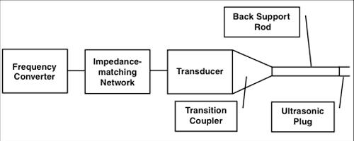
The main system components are a frequency converter, impedance-matching network, transducer, transition coupler, BSR, and ultrasonic plug (see Figure 3). The BSR is similar to a mandrel on a nonultrasonic tube drawing system; likewise, the ultrasonic plug (tuned to the operating frequency) replaces the standard tungsten carbide nib.
A mounting system is required to isolate the U-S system, which creates vibrations, from the machine’s frame, which is intended to be immobile. Mounting the U-S system directly to the machine’s frame would introduce vibrations to the machine that could have a catastrophic impact on the drawing process. Two types of mounting systems are used commonly to mount a U-S system: nodal and Elmore. Named for its inventor, the Elmore mount, which is designed to attach to the primary coupler, has a flange for a mounting sleeve, which is silver or copper braze. The entire system is then supported by the base of the mounting sleeve.
The end of the horn is threaded for attaching the BSR. Its diameter is determined by the largest BSR size planned for the UPD system. The primary coupler also provides a means for pumping process lubricant through the horn, into the BSR, and onto the forming tools.
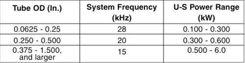
UPD systems are fundamentally different from UDD systems. The differences are related to the methods of ultrasonic energy application, power requirements, and the tube size range (see Figure 4). Furthermore, the physical size dictates the system’s operating frequency. Small-dimension arrays operate at higher frequencies; large units operate at lower frequencies.
Choosing UPD or UDD is based on the application. If it is a coil drawing or bull-wheel operation, it requires a die drive (UDD) system. Such systems now in production have power levels from 200 to 4,000 watts. In some cases of drawing thin-wall tube, UDD systems can be used on a draw bench. The UPD system applies only to straight-length bench drawing, and it has been evaluated up to 10 kW.
Power level requirements determine the number of transducers needed to achieve the proper impedance match, and therefore the vibratory power at the die end. Critical dimensions in this area apply to the length and diameter of full floating plugs and the estimated power level requirements. The length depends on the operating frequency and must be no greater than one-fourth the wavelength.
Note that as the tube diameter decreases, U-S systems become smaller. The amount of power is limited by transducer size, which also dictates the designs of multitransducer arrays. For example, for drawing tubing 1⁄8 to ¼ in. diameter at high speed, multitransducer arrays are used for developing more power and to match more closely the dynamic impedance of the process. Systems with up to eight transducers have been designed and built and used successfully.
Two items are new in the design of UPD and UDD systems. The first is by study and ingenuity, and the second is by chance.
The study portion involved redesign of the Elmore mount with an extension to effectively increase the cross section of the primary coupler and thus achieve a greater gain in the primary coupler horn of about l0 percent. In an impedance-matched system, this can result in 20 percent more power delivered to the plug or die.
The second derives from a request to change the BSR material. The request was to substitute INCONEL® 625 alloy for the conventional material, INCONEL 718 alloy. Samples of the alloys were obtained, and sound velocity measurements and vibrating characteristics indicated that they were similar in their ability to conduct ultrasonic power. However, they are not identical—during testing it was evident that the INCONEL 625 alloy bars vibrated noticeably longer than the INCONEL 718 alloy bars did.
The transducer, primary coupler, and horn also were changed to the INCONEL 625 alloy to maintain as good impedance match as practical. The result was that the chatter was eliminated, the draw speed was up to three times faster, and surface appeared smoother.
A recent study investigated three vibration modes—radial, torsional, and longitudinal—at 7.5, 15, 20, and 28 kHz. The frequencies were based on availability of transducer systems and suitable power capacity for the size of rod and wire being drawn. Two drawing machines were used: a hydraulic draw bench and a Herborn multistep capstan drawing machine.
The amount of force applied and the speed achieved in drawing tube or wire are similar to those in other metalworking processes involving friction. Materials generally don’t begin to deform until the applied forces overcome the “stick” portion of the characteristic stick-slip condition (see Figure 5). If the force stays constant and speed increases, normal friction behavior prevails until the speed of draw increases to a range of 90 to 120 FPM, when it enters the hydrodynamic phase. At this stage the surface tension created between the lubricants and the tube or pipe contributes to some back-pressure; this combination tends to thin out the lubricant film and thus reduces the frictional forces. The actual amount of force reduction depends on many variables, including the material of the workpiece (see Figure 6).
At high drawing speeds, materials deform more consistently and the end product is more uniform and with smoother surface finishes. If U-S energy is applied through this process, material behavior is apparently improved and the surface finish is dramatically improved.
Vibratory Mode Evaluation. Of the three vibrational modes, longitudinal has the optimum characteristics.


The Tube and Pipe Journal became the first magazine dedicated to serving the metal tube and pipe industry in 1990. Today, it remains the only North American publication devoted to this industry, and it has become the most trusted source of information for tube and pipe professionals.
start your free subscription
Easily access valuable industry resources now with full access to the digital edition of The Fabricator.

Easily access valuable industry resources now with full access to the digital edition of The Welder.

Easily access valuable industry resources now with full access to the digital edition of The Tube and Pipe Journal.

Easily access valuable industry resources now with full access to the digital edition of The Fabricator en Español.
In this episode of The Fabricator Podcast, Caleb Chamberlain, co-founder and CEO of OSH Cut, discusses his company’s...


