Contributing Writer
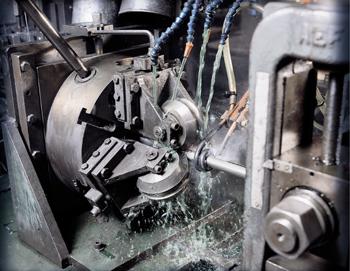 |
High-frequency induction (HFI) welding is used widely by the tube producing industry, but a large number of variables need to be controlled to perform the operation successfully.
In the HFI welding process, high-frequency current is induced in the open seam tube by an induction coil located ahead of (upstream from) the weld point (see Figure 1).
Tube edges are spaced apart when they move through the coil, forming an open V, which has an apex slightly ahead of the weld point. The coil does not make contact with the tube and acts as the primary of a high-frequency transformer. The open seam tube acts as a one-turn secondary.
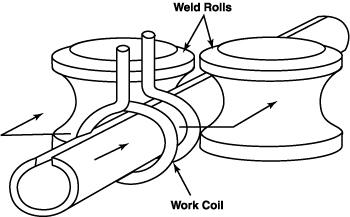 |
| Figure 1: In high-frequency induction (HFI) welding, a high-frequency electric current is induced in the open seam of a tube by an induction coil. |
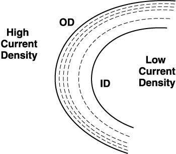
As in general induction heating applications, the induced current path in the workpiece tends to conform to the shape of the induction coil. Most of the induced current completes its path around the formed strip by flowing along the edges and crowding around the apex of the V-shaped opening in the strip.
High-frequency current density is the highest in the edges near the apex off the V and at the apex itself. The tube is heated rapidly, raising the edges to welding temperature when they arrive at the apex. Pressure rolls force the heated edges together, completing the weld.
The high frequency of the welding current creates concentrated heating along the V edges. A small portion of the total current also finds its way around the back of the formed strip. Unless the diameter of the tube is small compared with the V length, the current tends to flow along the edges of the tube forming the V.
 |
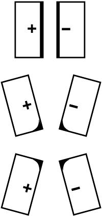
| Figure 2: Skin effect is the tendency of a high-frequency electric current to flow toward the surface of a tube. |
The welding process depends on two phenomena associated with high-frequency current—skin effect and proximity effect.
Skin effect is the tendency of the high-frequency current to concentrate at the surface of a conductor. In Figure 2, the high-frequency current flows in isolated conductors of various shapes. Almost the entire current flows in a shallow skin near the surface of the tube.
Proximity effect is the tendency of the high-frequency current in a pair of go/return conductors to concentrate in the portions of the conductor surfaces that are nearest each other. The physics behind proximity effect depends on the magnetic field surrounding the go/return conductors being more concentrated in the narrow space between them than it is elsewhere. The magnetic lines of force have less room and are squeezed closer together. It follows that proximity effect is stronger when the conductors are closer together and when the sides facing each other are wider.
 |
| Figure 3: Electric current concentrates on the parts of go/return conductor surfaces nearest each other, illustrating proximity effect. |
Two conditions must be present to obtain the best electrical conditions for the weld:
1. A maximum portion of the total high-frequency current should flow in the V.
2. The edges must be parallel in the V so that the heating of the seam will be uniform from inside to outside.
The first condition depends on such electrical factors as the design and placement of the welding contacts or coil and on a current impeding device mounted inside the tube.
The design is affected by the physical space available on the mill and the arrangement and size of the weld rolls. Encouraging high-frequency current flow in the V depends on the V dimensions and angle of opening. Therefore, even though the first condition is basically electrical, it ties in closely with the mill mechanicals.
The second condition depends wholly on mechanical factors such as the shape of the open tube and the edge condition of the strip. These can be influenced by what happens back in the mill breakdown passes and even at the slitter.
High-frequency welding is an electromechanical process. A generator supplies heat to the edges of the strip, but the squeeze rolls actually make the weld. If the edges are reaching the proper temperature and defective welds persist, chances are very good that the problem is in the mill setup or in the material.
In the final analysis, what happens in the V is all-important. Everything that happens there can affect weld quality and speed. Much of what happens in the V is a result of what already has happened, either in the mill itself or even before the strip or skelp enters the mill.
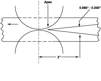 |
| Figure 4: In a high-frequency-welded tube, the tube edges meet each other upstream of the pressure roll centerline. |
Parallel edges in the V provide uniform heating between the inside and outside of the tube. Other V features, such as the location of the apex, the angle of opening, and the steadiness while running, also play important roles.
The Apex. In Figure 4, the point where the tube edges meet each other (i.e., the apex) is somewhat upstream of the pressure roll centerline. This happens because a small amount of material is squeezed out during welding. The apex completes the electrical circuit, and the high-frequency current from one edge turns around and goes back along the other.
In the space between the apex and the pressure roll centerline, no further heating is required because no current is flowing. In addition, the heat dissipates rapidly because of the high-temperature gradient between the hot edges and the remainder of the tube. Therefore, the apex should be as close as possible to the weld roll centerline so the temperature can remain high enough to make a good weld when pressure is applied.
This rapid heat dissipation causes attainable speed to more than double when the high-frequency power is doubled. The higher speed resulting from higher power allows less time for heat to be conducted away. Efficiency increases because a greater part of the heat that is developed electrically in the edges becomes useful.
Degree of V Opening. Keeping the apex as close as possible to the weld pressure centerline implies that the opening in the V is as wide as possible. However, practical limits apply.
The first limit is the mill's ability to hold the edges open without causing wrinkling or edge damage. The second limit is the reduction of the proximity effect between the two edges when they are farther apart. However, a V opening that is too small may promote pre-arcing and premature closing of the V, causing weld defects.
The V opening generally is satisfactory if the space between the edges at a point 2 inches upstream from the weld roll centerline is between 0.080 inch (2 millimeters) and 0.200 inch (5 millimeters), giving an included angle of between 2 and 7 degrees for carbon steel. A larger angle is desirable for stainless steel and nonferrous metals.
Parallel Edges. In high-frequency welding, a thin skin is melted on the face of the edges. This allows oxides and other undesirable materials to be squeezed out, helping to produce a clean, quality weld. With parallel edges, the oxides are squeezed out in both directions—nothing impedes them, and they do not have to travel farther than half the wall thickness.
If the inside edges come together first—as in a peaked tube—it is more difficult for the oxides to be squeezed out. Sometimes, a trough can form and act as a crucible for foreign material. This material floats on the melted steel near the hot inside edges. When this material is squeezed, it can become trapped in the weld interface and form inclusions.
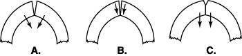 |
| Figure 5: The inside edges of a peaked tube first touch each other (5a), and the portion stuck together bends (5b). Then, the outside corners of the edge come together as if hinged on the inside (5c). |
Relative Motion. When the inside edges of a peaked tube first touch each other, they stick together (see Figure 5A). Shortly after (see Figure 5B), the portion that is stuck together bends. The outside corners then come together as if the edges were hinged on the inside (see Figure 5C).
The bending of the inner wall does less harm when welding steel than when welding materials such as aluminum, because steel has a wider plastic temperature range. Keeping the edges parallel prevents this relative motion and is likely to improve weld quality.
The V as an Electrical Load on a Generator. In the high-frequency process, when impeders and seam guides are used properly, the useful path along the V edges comprises the total load circuit, which is placed in the high-frequency generator. The current drawn from the generator by the V depends on the electrical impedance of the V.
This impedance, in turn, depends on the V dimensions. As the V is lengthened, the impedance increases, and the current decreases. Also, the reduced current now must heat more metal because of the longer V. Therefore, more power is needed to bring the weld area back to the welding temperature. As the wall thickness increases, the impedance decreases, and the current increases.
The impedance of the V needs to be reasonably close to the design value if full power is to be drawn from the high-frequency generator. Like the filament in a light bulb, the amount of power drawn depends on the resistance and the applied voltage, not on the size of the generating station. Therefore, for electrical reasons, V dimensions need to be as recommended, especially when full high-frequency generator output is desired.
The success of high-frequency welding depends on whether the forming section delivers steady, sliver-free, parallel edges to the V. The following are suggested guidelines for forming tooling.
Edge Breaking. Straight or modified edge breaking is useful because it gives the top of the tube its final radius in the first one or two passes. Sometimes, thin-wall tube is overformed to allow for springback. The fin passes should not be relied upon to form this radius—when they overform the tube, they tend to damage it and make the edges nonparallel.
This differs from usual electric resistance welding, in which large circular electrodes must act as high-current contacting devices and at the same time as rolls to form the edges down. However, recent developments in computer-controlled cage forming technology help to ensure flat, parallel edges and rapid changeover times when edge breaking is performed.
Fin Pass Compatibility. The progression in the fin passes should lead smoothly into the last fin pass shape. Each fin pass should do approximately the same amount of work—this helps avoid damaging the edges of an overworked fin pass.
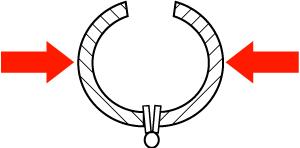 |
| Figure 6: Weld rolls must exert a large enough amount of force to close a tube even with the welder shut off and the edges cold. |
Weld Rolls and Last Fin Rolls. Getting parallel edges in the V requires correlation of the design of the last fin pass rolls and the weld rolls. The seam guide, along with any side rolls that may be used in this area, are for guidance only.
The function of the weld rolls in high-frequency welding is to force the heated edges together with enough pressure to make a good weld. The fin roll design should deliver the skelp completely formed, including the radius near the edges, but open at the top to the weld rolls. The opening is obtained as if a completely closed tube had been made of two halves connected by a piano hinge at the bottom and swung apart at the top (see Figure 6). The fin roll design accomplishes this without producing any concavity at the bottom of the tube.
Two-Roll Arrangement. Weld rolls must be capable of closing the tube with enough pressure to upset the edges, even with the welder shut off and the edges cold. This requires large horizontal components of force, as suggested in Figure 6. Using two side rolls accomplishes this task (see Figure 7).
A two-roll box is relatively economical to build. Only one screw needs to be adjusted during a run. It has right- and left-hand threads and moves the two rolls in and out together.
 |
| Figure 7: Many high-frequency welding systems use a two-roll arrangement to guide the tube. |
Under some circumstances, the two-roll arrangement may cause swirl marks on tubes. A common reason for this is improper forming, which requires the roll edges to exert higher-than-normal pressure. Swirl marks also may occur with high-strength materials that require high weld pressure. Frequently cleaning the roll edges with a flapper wheel or grinder helps to minimize marking.
Grinding rolls while they are in motion minimizes overgrinding or nicking the rolls, but extreme caution should be taken when doing so.
Three-Roll Arrangement. Many mill operators prefer a three-roll arrangement (see Figure 8) for small tubes (up to 4-1/2 inches outside diameter). This method almost eliminates swirl marks and also provides adjustment for correcting edge registration.
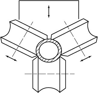 |
| Figure 8: A large number of mill operators use a three-roll arrangement for manufacturing small tubing. |
The three rolls, spaced 120 degrees apart, are mounted in clevises on a heavy-duty, three-jaw scroll chuck. They can be adjusted in and out together with the chuck screw. The chuck is mounted on a back plate, and the first adjustment is made with the three rolls closed tightly on a machined plug.
The backplate is adjusted vertically and laterally to bring the bottom roll into alignment with the mill pass height and with the mill centerline. The backplate then is locked and needs no further adjusting until the next roll change.
The clevises holding the two upper rolls are mounted in radial slides with adjusting screws. Both of these two rolls can be adjusted individually in addition to the common adjustment with the scroll chuck.
Last Fin Pass. The shape for the last fin pass in a tube mill illustrated in Figure 9 is designed to:
1. Present the tube to the weld rolls with the edge radius formed.
2. Have parallel edges through the V.
3. Provide a satisfactory V opening.
4. Be compatible with the weld roll design recommended previously.
5. Be simple to grind.
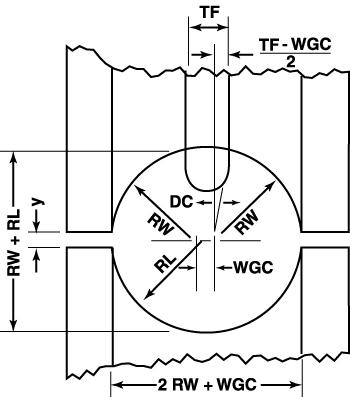 |
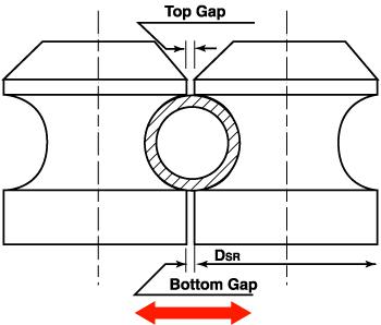
| Figure 9: In this design for the last fin pass in a tube mill, the bottom roll has a constant radius from a single center. |
In Figure 9, the bottom roll has a constant radius from a single center. Each of the two top roll halves also has a constant radius. However, the top roll radius (RW) is not equal to the lower roll radius (RL), and the centers from which the top radii are ground are displaced laterally by a distance (WGC). The fin is tapered at an angle.
The dimensions of the last fin pass are fixed by the following five criteria:
1. The top grinding radii are the same as the weld roll grinding radius (RW).
2. The girth (GF) is larger than the girth (GW) in the weld rolls by an amount equal to the squeezeout allowance (S).
3. The fin thickness (TF) is such that the opening between edges will fit with Figure 4.
4. The fin taper angle allows the tube edges to be perpendicular to the tangent.
5. The space "Y" between upper and lower roll flanges contains the strip without marking while providing some degree of operating adjustment.
High-frequency welding process is an efficient way to weld tube and pipe at high production rates. This process is heavily affected by two electrical phenomena—skin effect and proximity effect. However, the mechanical aspects that control the presentation of the edges together are not as easily understood.
Understanding how the mill mechanics affect the high-frequency welding process helps the tube and pipe producer lower costs and increase production rates.

The Tube and Pipe Journal became the first magazine dedicated to serving the metal tube and pipe industry in 1990. Today, it remains the only North American publication devoted to this industry, and it has become the most trusted source of information for tube and pipe professionals.
start your free subscription
Easily access valuable industry resources now with full access to the digital edition of The Fabricator.

Easily access valuable industry resources now with full access to the digital edition of The Welder.

Easily access valuable industry resources now with full access to the digital edition of The Tube and Pipe Journal.

Easily access valuable industry resources now with full access to the digital edition of The Fabricator en Español.
In this episode of The Fabricator Podcast, Caleb Chamberlain, co-founder and CEO of OSH Cut, discusses his company’s...