


Vice President of Sales and Marketing

Although most roll formed products don’t need welds, the market for welded profiles has been growing for more than a decade. Matching the welding process to the profile is a necessary early step in planning and developing a line for the forming and welding process. Photo courtesy of TRUMPF Inc.
Welded profile applications have been steadily increasing over the last 10 to 15 years, driven mainly by the automotive industry. As they look for ways to increase strength and reduce weight, automobile engineers continually research materials and forming processes to find the best combinations of part design, weight, and strength. To get a piece of this growing pie, roll formers need to consider manufacturability and reliability. How easy or difficult will it be to manufacture this profile? How stiff and strong will it be? Will the product be consistent from one run to the next and one day to the next?
For experienced roll formers, these questions have more to do with welding than with roll forming. Although many welding technologies have been used on tube and pipe mills, three have come to the forefront: tungsten inert gas (TIG), formally identified by the American Welding Society as gas tungsten arc welding (GTAW); laser beam welding (LBW); and high-frequency induction (HFI), formally known as induction resistance seam welding (RSEW-I). These technologies can be divided into two groups, fusion welding and forge welding. GTAW and laser are fusion welding technologies, relying mainly on heat to fuse the material. HFI is a forge welding technology, which uses a combination of heat and pressure.
Although tube, pipe, and profiles are made from a great variety of materials, this article concentrates on carbon steel, alloy steel, and stainless steel.
Fusion welding is a generic term for welding processes that rely on melting to join materials of similar compositions and melting points. For roll forming applications, a filler metal typically is not used.
GTAW Basics. GTAW generates an electric arc between a nonconsumable tungsten electrode and the workpiece to produce the weld. The weld area is protected from atmospheric contamination by a shielding gas, either a single gas or a mixture of gases. GTAW sometimes is called a “collapse” melting method, which implies that the weld puddle collapses back on itself as it solidifies. Because of this, the effect of gravity is a concern for two reasons. First, the weld seam must be in the 12 o’clock position. Second, if the puddle becomes too hot, it will drop and the weld joint will be defective.
GTAW Equipment. The equipment necessary to perform GTAW successfully differs little from basic manual welding equipment. The power source is available from most local welding supply houses.
When choosing a power source, it is important to look for specific features, primarily the rated output power, which is the main factor that determines how fast it can weld. This is important because the production speed of the mill usually is limited by the GTAW speed. Unfortunately, many power supplies are advertised with power output ratings at only 60 percent duty cycle. This means they can overheat if operated at full power for more than 60 percent of the time. For a continuous application like roll forming, it’s important to know the power output at 100 percent duty cycle.
The practical limit for inline welding is approximately 350 amps. Delivering more current to the weld pool doesn’t usually translate into increased weld speed. It is for this reason that multiple-torch or multicathode systems are available.
Another consideration for the power supply is the ability to provide a pulsed current, which refers to two current levels. The higher current level, the pulse, heats the weld pool; the lower current level, or background current, allows the weld pool to cool. Pulsed current puts less heat into the workpiece, reducing distortion as it cools. It also increases the arc stability by stiffening the arc. The result is deeper weld penetration and higher welding speeds.
In some manual welding applications, a back-and-forth (weaving) or circular motion is used to achieve the best possible weld quality. For the same effect when using a stationary torch, magnetic oscillators are used to manipulate the weld arc.

Figure 1
The edges to be welded should be as perfectly aligned as possible as shown in these
illustrations of square and closed square butt joints.
In addition to sufficient weld current, sufficient weld voltage is also necessary. As Joule’s law states, power equals voltage multiplied by current (P = V x I). Since most power supplies provide constant current, keeping the voltage constant is essential for constant power (in the weld, this means constant heat). In arc welding, the voltage is directly proportional to arc length (the distance from electrode tip to workpiece).
To maintain a constant arc length (or arc voltage) automatically, an arc voltage controller (AVC) can be used. The AVC includes a motorized torch mount that moves the torch vertically as needed to change the arc length. Coupling this with an electronic controller that monitors arc voltage ensures that the system maintains a constant arc length.
While the arc length doesn’t vary greatly, it does increase over time as the tungsten electrode degrades and becomes shorter. For thin-walled profiles or sensitive applications, this minor arc length change can have a significant effect on weld quality. The downside is that AVCs allow the welding system to continue even if the setup is not optimal. Some mill operators believe it is better to stop the line and change to a new electrode as it degrades.
GTAW Inline Application. For an inline GTAW application, the most important consideration is how to properly present and maintain the profile’s strip edges for a butt weld joint before and during welding. To achieve this, both good forming tool design and weld squeeze box design are required. The roll tooling must be designed so that the strip edges are formed in a closed square butt joint in which the two strip edges are flat and parallel to each other (see Figure 1).
The weld box must be able to close the open seam, if necessary, and hold the profile closed during the welding process. This typically requires two pairs of roll tooling. For faster welding speeds, the addition of a third roll pair may be necessary to hold the profile closed for a longer amount of time to allow the weld puddle to solidify sufficiently. Higher weld speeds are common on thinner material gauges and when using multicathode torches. In some cases, a solid contoured weld block is used in place of rotating rolls.
It is best to have a weld roll material that is nonmagnetic so that it does not interfere with the weld arc. Depending on the application, it may be beneficial to use the torch’s cooling circuit to cool the weld rolls, the roll shafts, or both.
Laser Basics. Laser beam welding (LBW) provides a concentrated heat source, allowing for narrow, deep welds and relatively high welding rates.
Like GTAW, LBW is a fusion process; however, the similarity ends here. In laser welding the two main processes are heat conduction welding and deep-penetration welding, also known as keyhole welding (see Figure 2). In heat conduction welding, the materials to be joined are melted by absorption of the laser beam at the material surface—the solidified melt joins the materials. Welding penetration depths in this context typically are below 2 mm.
Deep-penetration welding is based on the creation of a vapor capillary inside the material by local heating to the evaporation temperature. The resulting vapor pressure inside the material creates a capillary, which moves through the material along the weld seam. The hydrostatic pressure, the surface tension of the pool, and the vapor pressure inside the capillary reach equilibrium, preventing the capillary, often called a keyhole, from collapsing.
While GTAW requires a closed square butt joint, laser welding can be used for other applications—flange joints, lap joints, fillet seam joints, and spot welds.
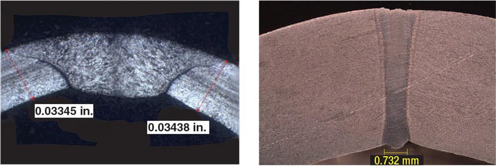
Figure 2
A weld made by the GTAW process (left) is wide compared to one made by a laser beam
(right). While the laser’s focused power makes a narrower, hotter weld pool, the trade-off
is that the weld seam must be tightly controlled so it doesn’t wander left or right. Photo
courtesy of IPG Photonics Corp.
Laser Equipment. The three main components in a laser system are the beam generator, the beam delivery system, and the focusing optics. The most common types of beam generators today are CO2, Nd:YAG (neodymium-doped yttrium aluminum garnet), and fiber.
The oldest technology is CO2. It has been the industry workhorse for many years and continues to be a solid performer. These lasers generate a beam by applying electrical energy to an enclosed mixture of gases, which stimulates the CO2 molecule to give off photons of light, or heat. The beam is delivered to the focusing optics via a series of bellows pressurized with compressed air or nitrogen gas to keep out any dust or particulate, as well as a set of mirrors.
Nd:YAG lasers are solid-state units that pump a high-intensity light source (flash lamps or diodes) into a specially coated crystal rod, which causes it to generate the beam. Although the beam quality is not as good as that of a CO2 laser, they have few if any moving parts and the beam can be transmitted through a flexible fiber-optic cable.
Fiber lasers generate the beam by pumping diode light directly into an optical fiber. Fiber lasers offer excellent beam quality, fiber-optic beam delivery, and have no moving parts (see Figure 3).
Laser Inline Application. As with GTAW of butt joints, laser welding requires even more attention to the strip edge presentation. However, laser welding can be three to five times faster than GTAW. As a result of this increased speed, the weld puddle moves downstream much faster and farther than with GTAW. To ensure that the puddle has sufficient time to solidify without springing back open, the profile must be kept closed for a longer time. This usually is accomplished by adding a third pair of squeeze rolls.
Because the laser’s spot size is very small, weld seam stability is crucial. This requires both a very good roll tooling design and a well-aligned, stable roll forming machine. It also requires a high-quality strip stock with minimal camber and relatively close-tolerance gauge control.
Forge welding uses heat and a hammering or pressing process to make the joint. Although it is not necessary to actually melt the metal being joined, it is necessary to have sufficient forging squeeze pressure.
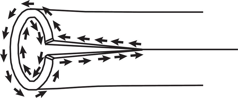
HFI Basics. HFI welding uses the same principles as induction heating. It is the process of heating an electrically conducting object (usually a metal) by electromagnetic induction, where eddy currents are generated within the metal and electrical resistance to this current flow leads to heating of the metal. The HFI process depends on two phenomena associated with high-frequency current: skin effect and proximity effect.
The skin effect is the tendency of HF current to stay close to the surface of the conductor, which is a function of the frequency (see Figure 4). For HFI welding, frequencies from 200 kHz to 400 kHz are typical.
It is important to understand how current flows in a formed profile (see Figure 5).
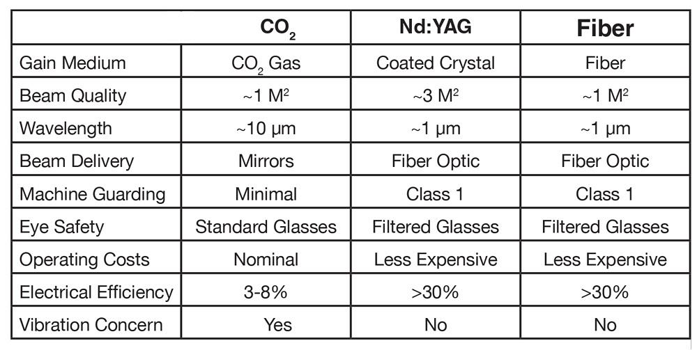
Figure 3
Focusing the current where it is needed is a necessary step for utilizing the other phenomenon, the proximity effect. This is the tendency for the induced currents to concentrate where two conductors are closest to each other.
HFI Equipment. The HFI welding process starts with the HF induction power source. Regardless of the manufacturer, HFI welders all share the same six basic components:
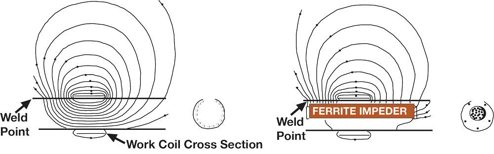
As mentioned previously, a ferrite impeder is required for HFI welding. The impeder must be specifically located within the induction coil. This is done by attaching the impeder to a support tube that is hung from a mounting bracket at a point upstream of the weld area. Note that the impeder requires cooling water to prevent it from overheating. The mounting assembly must be able to accommodate the supply of cooling water.
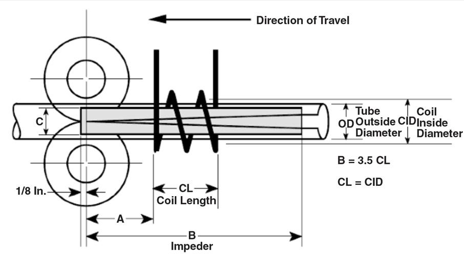
Proper placement and sizing of the induction work coil relative to the weld roll centerline is important for successful and efficient HFI welding, as is the placement and sizing of the impeder (see Figure 7).
To forge the edges together, a weld squeeze roll box is used. The configuration of the box is generally dictated by the size and profile itself. It is important to utilize a configuration that will allow the heated strip edges to be adequately pressed together.
HFI Inline Application. Of the three methods described here, HFI requires the most attention to detail. The weld roll geometry, the strip edge presentation, the impeder, and the work coil must complement each other to be successful. However, once these are established, HFI welding outproduces the other two methods.
Because HFI heats the strip edges in an open atmosphere, oxides and other impurities form in the weld joint, so squeeze pressure is needed to upset some of the material, or force it out of the weld. This material forms two protrusions, one on the ID and on the OD, known as upsets or scarf.
Some applications allow a rolling process that reduces the protrusion’s profile, but many applications require its removal. A weld bead trimmer uses a carbide cutting tool to skive, scarf, or trim the upset bead from the joint.
In most cases, the weld bead is scarfed, cut, and dropped into a bin that the mill operator empties periodically. If the scarfed weld bead is a continuous strand of material, it can be threaded onto a winder that gathers and stores the bead.
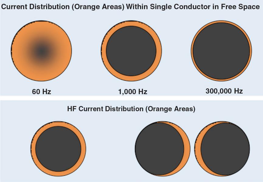
Figure 4
Household current, 60 Hz, tends to penetrate the conductor; as the frequency increases,
the skin effect—the tendency for the current to ride the surface—increases (top). The
proximity effect concentrates the current that flows through two conductors near each
other.
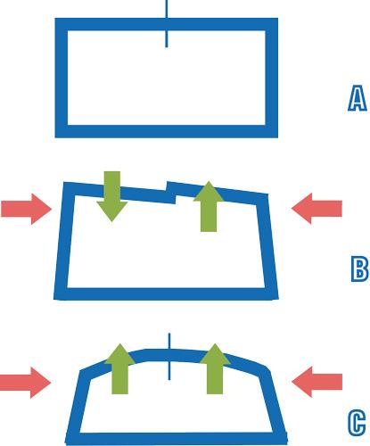
The squeeze pressure has another result that must be managed. Depending on the material, edge alignment, and squeeze pressure, the edges have the potential to overlap each other. To prevent the edge mismatch that leads to the overlap condition, the tooling design should be changed to allow a slight crown in both legs (see Figure 8). In this case, when squeeze pressure is applied from the sides, the natural tendency is for the legs to both move up and outward against the upper weld rolls. This crowning strategy increases the chances of getting proper strip edge registration and forge pressure. The profile can be reshaped in subsequent roll passes.
Regardless of the welding method, some consideration must be given to cooling the weld seam. If the part leaves the mill before the weld seam has cooled, it probably will bow and twist as it cools. In most cases, a water quench station using the mill coolant is sufficient. The welding speed usually dictates the length of the cooling section; a common rule of thumb calls for 1 foot of cooling length for every 10 FPM of welding speed. Keep in mind that this is just a starting point; the material grade and metallurgical properties of the alloy also come into play. Some materials require a soak time or an air-cooling time, or both, before the water quench. In addition, some materials may require that the entire welding and cooling occur within the protective gas atmosphere.
Another consideration is the mill’s drive system, which must have good speed regulation, especially if it uses multiple drive motors. A separate motor to drive the roll passes after the welding station is preferred so that the profile can be kept in constant tension as it is welded. This tension is helpful for closing the weld seam, and keeping it closed, while it is being welded. Lack of strip tension can be likened to pushing a wet noodle through the weld box. Although strip tension can be achieved by progression, or step-up, in the roll tooling design, it is far easier to trim the speed of a separate motor.
The decision to use GTAW is driven by a few key points. First, the weld seam must be continuous and at the 12 o’clock orientation. If the limited speed capability is acceptable and equipment cost is a concern, then GTAW is generally the right choice. It is important to note that a GTAW mill can be upgraded to LBW without too much trouble. GTAW can be considered an intermediate step before transitioning to LBW. It’s also possible to set up the mill so that it can be changed back and forth between GTAW and LBW.
LBW is the preferred method in situations where a continuous seam is not possible, where the seam is not oriented at 12 o’clock, or the joint required is not a butt joint. LBW is also useful in situations where GTAW speeds are too slow. LBW is clearly the most versatile method.
HFI welding’s biggest advantage is speed. If a continuous seam is possible and no other factors limit the welding speed, then generally HFI is the right choice, especially if the application calls for high-volume production.
The processes are summarized in Figure 9.

The Tube and Pipe Journal became the first magazine dedicated to serving the metal tube and pipe industry in 1990. Today, it remains the only North American publication devoted to this industry, and it has become the most trusted source of information for tube and pipe professionals.
start your free subscription
Easily access valuable industry resources now with full access to the digital edition of The Fabricator.

Easily access valuable industry resources now with full access to the digital edition of The Welder.

Easily access valuable industry resources now with full access to the digital edition of The Tube and Pipe Journal.

Easily access valuable industry resources now with full access to the digital edition of The Fabricator en Español.
In this episode of The Fabricator Podcast, Caleb Chamberlain, co-founder and CEO of OSH Cut, discusses his company’s...


