


Vice President
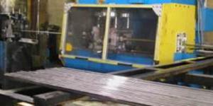 |
| Figure 1 Tube Mill Cutoff - Left to Right - Single Cut |
A comprehensive tooling plan that includes setting up and maintaining sufficient tools according to the original design manufacturer's (ODM) specifications is critical for efficient high-speed tube mill operation. The tube mill cutoff component (Figure 1) is an integral part of this plan.
Keep at least three master die sets on hand at all times for each tube mill cutoff—one at production, one preset for the next scheduled run, and one at repair/standby. These die sets should shift position at each tube mill size change.
Three sets of die jaws for each tube size should always be on hand—one set at production, one set at production standby, and one set at repair.
Maintain a six-week supply of blades at all times.
All tooling should be cleaned and stored near a toolroom, and master die set setup always should be performed in a clean toolroom. Proper setup entails the following steps:
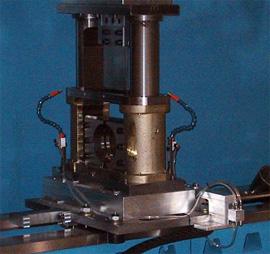 |
| Figure 2 Single-cut Die Set - Blade Lubrication |
Cleanness is a must throughout a tube mill. Power-wash the production master die set before removing it from the die set carriages. Power-wash the die set carriages after the production master die set is removed. (A simple power washer is a garden hose and gate valve attached to a sizing mill coolant line).
When the die set carriages are clean and free of all debris, install the preset master die set. Adjust the shear blade lubrication nozzles to ensure blade lubricant delivery to all working surfaces of the tooling (see Figure 2). Set the blade lubricant system to deliver lubricant just before each cut.
Insufficient tooling lubricant is another major cause of poor cut quality and totally outrageous tooling costs.
High blade speeds, soft or killed steels, and other factors can contribute to high-heat conditions at the default 10 percent of tube wall thickness blade-to-die-jaw clearance. Any one (or all) of the following can solve the problem:


The Tube and Pipe Journal became the first magazine dedicated to serving the metal tube and pipe industry in 1990. Today, it remains the only North American publication devoted to this industry, and it has become the most trusted source of information for tube and pipe professionals.
start your free subscription
Easily access valuable industry resources now with full access to the digital edition of The Fabricator.

Easily access valuable industry resources now with full access to the digital edition of The Welder.

Easily access valuable industry resources now with full access to the digital edition of The Tube and Pipe Journal.

Easily access valuable industry resources now with full access to the digital edition of The Fabricator en Español.
In this episode of The Fabricator Podcast, Caleb Chamberlain, co-founder and CEO of OSH Cut, discusses his company’s...


