


Laser-based skelp edge inspection enhances quality control from the start
Precise measuring system upstream prepares edges for welding downstream
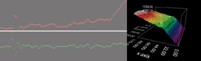
Figure 1: The red and green lines represent the edge surface (left). The red line shows the profile; the green line shows defect detection (deviation from a good edge). Because the green line shows little deviation, the edge is satisfactory and likely will result in a good weld. Likewise, in the multicolored graph, the gradual slope and consistent surface along the X axis indicate an edge with good continuity (right).
As every tube or pipe mill operator is well aware, a high-quality weld seam starts with coil that has good edges. The problem is that good, consistent edges are almost impossible to obtain by trimming, whether working with master coils or slit mults. Slitting affects surface appearance, width dimension, flatness, camber, and edge wave.
Depending on the severity, these defects can affect the final quality and acceptability of the pipe or tube coming off the mill. Edges that don’t smooth out in the fin passes cannot be presented parallel to one another at the weld point, heat unevenly, and the result will be periodic or continuous weld splits.
Meanwhile, the state of competition in this industry is severe, and this won’t change anytime soon. Pipe- and tubemakers must execute every process to the fullest, and measuring overall equipment effectiveness (OEE) can be a critical step in uncovering bottlenecks and finding root causes to quality problems. Monitoring the strip’s edges, and preparing them properly before the material enters the mill, can be an integral part of this effort.
Edge Conditions
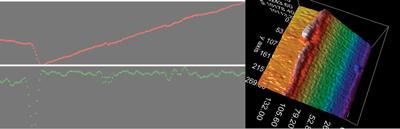
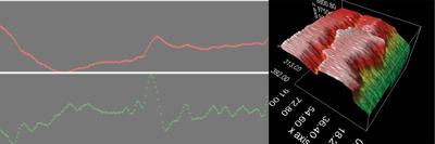
When skelp is processed through a trimming process as in a rotary shearing unit, material is forced between pairs of offset circular blades. The blades overlap each other, causing a shearing action that separates the material. The blades partially cut the material from the top and bottom, but they don’t sever it; the remainder is fractured or broken. In many cases, the break is clean and the edges are suitable for welding (see Figure 1). However, torn edges, often the product of improper setup or dull or broken cutting tools, produce undesirable edge conditions (see Figure 2 and Figure 3).
Inspection System Setup and Use
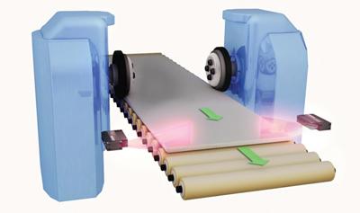
An accurate skelp edge inspection can be carried out by a laser profile system using two sensors, one on each side of the infeed coil (see Figure 4). The ideal scanner location is where the infeed process is relatively stable, usually after pressure rollers. The system is set up and calibrated to take into consideration the specific needs of the process—that is, the resolution and accuracy of the scanners are suited to the application so the system works within the intended tolerance limits.
Filtering of the laser line before processing ensures that good data is passed to the software. The software also takes into account any movement of the laser line within the operating window. Once the setup is complete, the system measures skelp width, skelp thickness, burr, shear angle, and penetration-to-break ratio. In addition, it looks for edge discontinuities, which can cause weak welds.
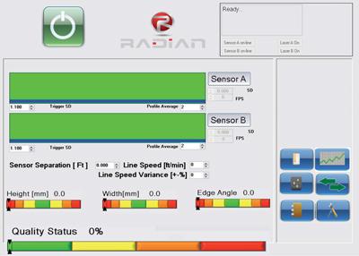
When the system is up and running and the mill is making tube or pipe, the human-machine interface (HMI) provides a continually updated visual indication of the control parameters (see Figure 5). An encoder signal tracks any discontinuities and alerts the operators downstream as each discontinuity moves through the mill.
Programming the System. The system uses a library of reference parameters as a baseline, and compares the measurements of the incoming skelp against a selected reference in its library. The operator doesn’t have to create the reference library manually; the software’s training mode collects data and calculates averages and standard deviations, then uses this information to build the control limit library.
The input/output (I/O) signals are mapped and linked to a programmable logic controller (PLC). The outputs can be based on either individual control parameters or an overall quality indicator.
Using the Data. The system has two broad uses. First is the ability to alert the operator to a production problem. Alerts are based on a defined set of production rules. Each event generates an alert (HMI, light tower, or marking system) and can even generate a corrective action list on the HMI. Monitoring the data in a summarized manner allows for faster communication of the skelp metrics and quicker decision-making. The system can initiate a shutdown sequence if the event is severe.
The second is statistical process control (SPC). The system’s built-in SPC system collects comparative data over time, charts the data based on a time or position axis, and publishes customizable reports for review by production and quality control personnel. The reporting system can either be driven manually or by an automated process based on an event, a schedule, or a preset rule.
These two abilities allow the operators to work toward making products with less variation and less scrap, thereby improving quality and productivity and allowing the quality department to scout for patterns and preventive strategies.
About the Author
About the Publication

subscribe now

The Tube and Pipe Journal became the first magazine dedicated to serving the metal tube and pipe industry in 1990. Today, it remains the only North American publication devoted to this industry, and it has become the most trusted source of information for tube and pipe professionals.
start your free subscription- Stay connected from anywhere

Easily access valuable industry resources now with full access to the digital edition of The Fabricator.

Easily access valuable industry resources now with full access to the digital edition of The Welder.

Easily access valuable industry resources now with full access to the digital edition of The Tube and Pipe Journal.

Easily access valuable industry resources now with full access to the digital edition of The Fabricator en Español.
- Podcasting

In this episode of The Fabricator Podcast, Caleb Chamberlain, co-founder and CEO of OSH Cut, discusses his company’s...
- Trending Articles
1
Team Industries names director of advanced technology and manufacturing

2
Orbital tube welding webinar to be held April 23

3
Chain hoist offers 60-ft. remote control range

4
Push-feeding saw station cuts nonferrous metals

5
Corrosion-inhibiting coating can be peeled off after use
