


Contributing Writer
 |
In the simplest terms, tube and pipe is produced by a mill that rolls flat stock material into a round shape, welds the two edges together, and cuts the resulting homogeneous pipe to some predetermined length.
The subject of this article is the radio frequency (RF) generator that supplies the power to heat the edges of the material sufficiently to cause a weld. This generator outputs power to a multiturned coil around the pipe, which transfers the power to the point at which the material edges first come together.
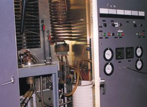
The first time you look at a tube and pipe welding generator, it can be intimidating. Even an experienced technician will stop and analyze an RF welding generator before blindly proceeding to disassemble any of the components. As with most mechanical or electronic devices, separating the unit into functional sections will usually allow a better understanding of its operation.
The analysis can begin by separating the RF welding generator into its major pieces or subassemblies. Most generators include the following (see Figure 1):
1. A housing or cabinet in which all the components are placed.
2. A power supply to convert the line voltage to DC.
3. An oscillator section that includes the power tube and associated circuitry.
4. A cooling system to remove heat from the power tube and other related components.
5. A matching section.
6. A control section that includes circuit breakers, power adjustment knobs, and other external adjustment controls or information displays.
7. A mechanical and output section that contains any special fixtures, robotics, loading, quenching devices, etc., that are usually not directly part of the generator but work in conjunction with it.
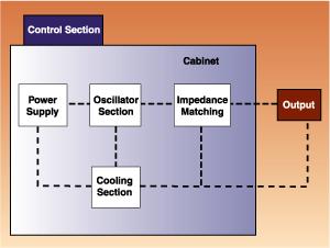 |
| Figure 1: The main sections of a welding generator are shown here. |
If possible, allow a maintenance technician to go beyond general maintenance when he first works on a unit. You probably have a machine that could use a lot of maintenance, almost to the point of rebuilding the machine completely. Rebuilding does not take much longer than extensive maintenance, but it guarantees a thorough repair job, allows a preventive maintenance program to be started, and allows the technician a chance to really learn how the various parts of the generator work.
This article explains how to get each section of an RF welding generator into good working order. Once the generator is repaired and put on a preventive maintenance schedule, it should stay in top condition.
Remember that safety cannot be stressed enough. Tube mill RF welding generators operate at high voltages and must be disconnected or locked out before any maintenance can be performed.
Before starting, you must complete a few general tasks. First, locate the schematic diagram for the generator. If it is not available, draw one as detailed as possible. Include all numbers on components, values, types of materials used, even the dimensions of the coils that are used. Then photograph the unit inside and out.
Pay particular attention to component placement. Take time to identify each component and its purpose. This, of course, is much easier with a schematic, but it must be done regardless.
During this time, the unit should be vacuumed to remove all the accumulated dust and dirt. This dirt may have to be loosened with a brush first. Do not use an air hose to blow the dust out, because you will probably just blow it further into the generator.
Look at all the connections, components, and insulators for any signs of overheating or arcing. Check screw heads that may have loosened; are corona being generated around them? Eventually, the corona will start to track carbon across insulators, and arcing will occur. An estimated 80 percent of these problems can be identified by a good visual inspection.
The cabinet of the RF welding generator is much more than a case in which to store everything. Most of the safety interlocks are located somewhere on the cabinet doors. These interlocks, whether mechanical or mercury switches or pin-and-socket types, should be tested for operation.
The doors should also include some RF gasket or spring stock material to keep energy from radiating from the enclosure. The inside enclosures should also be checked to ensure that energy is not getting into other components, such as timers, meters, or controls, which could cause false triggers and erroneous readings.
Some units also have mechanical shorting mechanisms connected to the doors that automatically connect all high-voltage components to ground if the enclosure is opened. Most of the other components are somehow connected to the cabinet, so double-check for tight, clean connections, and check again for signs of arcing.
Although they are part of the cooling section, the air filters are located on the cabinets and should be checked for dirt that will block proper airflow. Also, objects such as boxes should be cleared away so they do not block the vents. Some systems have an airflow and/or pressure switch interlocked to the power to prevent operation with improper airflow. This should also be tested for operation.
The power supply develops the high voltage required for the operation of the oscillator tube, as well as filament voltage. In most cases, it also contains the connections to the outside power source and the main disconnect switch and circuit breakers. It may also include auxiliary power sources for special equipment associated with the output section. All connections should be cleaned, tightened, inspected for oxidation, discoloration, pitting, or arcing, and repaired or replaced as required.
Filament voltage is generally alternating current (AC) and is supplied through a step-down transformer. Since most power tube filaments operate at low voltage and high current, the interconnection cables will not necessarily be highly insulated but will be made of heavy-gauge wire (usually stranded copper for current-carrying capability and heat dissipation). Terminations are typically heavy spade lugs that are kept as short as possible.
Clean, tight connections are particularly important because of the high currents involved. For example, a resistance of only 1100 ohm on a typical tube that requires 100 amps will result in a loss of one volt to the tube filament. Since a modern tube requires a filament voltage of 7 to 13 volts, the voltage loss will almost always result in insufficient output power to the load. Filament voltage should always be checked at the tube terminals with a good-quality meter.
High voltage (direct current (DC) for the power tube anode) can be generated by tube circuits (vacuum, mercury vapor, or hydrogen-filled tubes) or by solid-state rectifiers. In this case, the voltages will be high, usually thousands of volts, and the currents relatively low. Clean, tight connections are also important here to prevent corona.
Spacing of components is also important to prevent arcing. Spacing will differ depending on the voltage, insulation material used, etc., so original material should be replaced at the same distance as that originally provided by the manufacturer.
The oscillator contains the power tube and the associated circuitry. All oscillators have a tank circuit consisting of at least one capacitor and a coil in parallel that determines the frequency of operation. They also contain some method of feedback to the grid circuit to sustain oscillations and connections to the tube filaments.
Other components, called suppressors, are connected to prevent spurious oscillations at unwanted frequencies. Suppressors can be capacitors connected to various tube elements or frequency traps made up of any combination of resistors, capacitors, or inductors. Beads of ferrite material are also used to absorb unwanted RF energy.
It is not important which components are used, as long as they are repaired and replaced as necessary. Often, the technician will not know the purpose of these components and will leave them out of the circuit or replace them with whatever components are available, not necessarily of the same value. The generator might work fine without the correct components. However, they are there to protect against a transient condition, as a fuse is, so it is important that they be used correctly.
The purpose of the photographs taken before disassembly is to ensure that the components, including routing or interconnecting wires, are replaced in their exact original positions. A component or wire placed incorrectly can act as an antenna and channel RF energy from the cabinet to an inappropriate area. This danger can be minimized by replacing things exactly as they were.
Again, a good visual inspection is the technician's best ally. The RF causes most of the ionization and carbon tracking found in a generator. Carbon tracking often starts in an area that is covered, such as under a screw head, so disassembly is needed.
Cleaning can be done only with certain chemicals, and alcohol is probably the safest. Although it is not a solvent for all materials, it will not leave a residue and is relatively safe from flash fires. Some insulators may have to be completely removed and cleaned with a detergent or sandblasted to remove carbon. If insulators show any signs of deterioration, they should be replaced with the same material.
Overheating is probably the biggest enemy of components, especially power tubes. Over-voltage on the filament will shorten its life considerably, and improper cooling will cause outgassing of the other elements and, in extreme cases, melting of the tube anode and/or grids. Most of the generators used in induction heating applications use water cooling, while dielectric generators rely more on air or radiation cooling.
If the previous recommendations have been followed, the blower motors, air directors, and filters have already been inspected and/or changed. Air is often used with water to cool the filament and grid terminals. Tubes can be removed, washed in water, and scrubbed with a medium bristle brush. They must be completely dried, dipped in alcohol to displace the water, and then air-dried or blow-dried (a warm hair dryer is sufficient).
Radiation-cooled tubes (large glass bottles without fins that are usually limited to rectifiers in power supplies) can be washed the same way. Gloves should be worn when handling all insulators, including glass envelopes and tube ceramics, to prevent skin oils from touching them. These oils contain carbon that will cause problems when exposed to RF and high voltages, eventually tracking as discussed previously.Many of the larger tubes use air to cool the filament and grid terminals, even though the anode is water-cooled. Temperature-sensitive paint or labels placed on the tube seals will give a good indication of any potential overheating problems.
An air velocity meter is also available to check airflow. Also, make sure that the airflow interlocks are operating. Some generators have a time delay system that will keep the air blowers and water cooling pumps operating for a few minutes after the filament and high voltages are shut off, so make sure these circuits are not bypassed.
Water cooling is the other usual way to cool RF tubes. Two elements are needed for proper operation and long life: water purity and sufficient coolant flow. Cooling pumps supplied by the equipment manufacturer are adequate to provide the minimum flow rate specified on the tube data sheet. Pump size and hose diameters must be maintained.
Ordinary tap water is not sufficient for cooling systems. Distilled water must be used. Water quality must be periodically checked to ensure resistivity. Since the water column is exposed to the anode high voltage at one end and grounded at the other, it acts as a resistor. The more pure the water, the higher the resistance and the less power wasted by heating the water. Water should be maintained at a minimum of 1 megohm-cm at 25 degrees Celsius.
Water purity can easily be compromised by oxygen, which can form a copper oxide on the anode cooling surfaces, destroying the heat conductivity of the copper, or cause electrolysis. Electrolysis can actually destroy the cooling passages in tubes and other system components. In extreme cases, oxide deposits can plug cooling passages and stop coolant flow.
Any components that are replaced in the cooling system should be replaced with the same material. Avoid using iron or galvanized fittings or pipe, since they will contaminate the water system in a matter of hours.
The matching section ensures that the maximum possible power available is transferred from the generator to the load by matching the two sections by impedance. The impedance of the generator is essentially constant, but the load changes depending on the particular workpiece being used. Matching is either done automatically or set for optimum conditions manually.
The matching section can be identified by controls labeled "load tuning," "load matching," or "output tuning." The section can contain any combination of capacitors, coils, transformers, variable ratio transformers, or auto-transformers. There are probably as many schemes to match impedance as there are generator manufacturers, but all have the components mounted in an enclosure to ensure all connections remain clean and tight.
This section requires little maintenance except to ensure that everything is making good electrical contact. Since all the power must pass through this section, it is possible to have power losses, even because of a mismatch of impedances. This is usually obvious since some components will quickly overheat, which causes heavy discoloration.
Machine control panels come in many different configurations, from very elaborate to a simple on-off switch. In general, they require little care except for an occasional vacuuming and wiping down with alcohol. The voltages and currents involved are relatively low, so arcing and corona are rarely a problem.
Any circuit breakers located in this section should be tested for proper operation, as should indicator lamps and other switches. Meters on the panel should be calibrated periodically. These meters might be part of the cabinet section and usually measure anode voltage, anode current, and grid current. Since they are the first indication of some variance in the operation of the equipment, they should be kept in proper repair and calibrated on a periodic basis.
More machines are now being produced or retrofitted with programmable logic controls. Essentially, they are embedded computer-controlled devices that receive operating status information from various sensors regarding open interlocks, over-voltage, currents or temperature, low or high air or water flow, etc. Depending on their programming, they can also adjust parameters, shut down the equipment, sound alarms, etc.
Programmable logic controls are low-maintenance devices, and periodic cleaning and tightening of the sensors are usually sufficient for proper operation. They are usually purchased by the generator manufacturer for inclusion in the generator, so they will have their own maintenance/repair instructions.
The mechanical and output section is a catch-all section for the other parts to the system where the actual work is done. In the case of a tube and pipe mill, this section is the relatively simple multiturned coil previously discussed and does not contain elaborate mechanisms.
Maintenance is similar to that for the control panel, although it is often more complicated because of the combination of motors and mechanical devices that may be used. Motors need controllers and limit switches that require testing and adjusting, as well as mechanisms that have to be inspected for smooth operation and proper lubrication. Again, much of this equipment is purchased by the generator manufacturer or even adapted locally by the owner.
The electronics portion has high RF on it, which is the output from the matching section, so the same rules apply as on the other RF-carrying elements. During operation of the equipment, watch for arcing at the work coils or platens. Not only could arcing ruin the work, but the RF can be reflected through the matching section and into the oscillator, causing arcing on some of the components.
It certainly would not be effective to do all this work rebuilding a generator without keeping it in this condition. Certain things have to be checked more frequently at some locations than others, and there can be different time intervals for component testing. Each tube manufacturer must determine its own conditions, but following is a recommended program for a 40-hour-a-week operation:
1. Check and record all meter readings, looking for any obvious changes.
2. Check and/or replace filters and inspect all cooling fans and water pumps for proper operation.
3. Ensure that the resistivity of the water system meets minimum requirements.
4. Open the cabinet and visually inspect the oscillator section.
1. Inspect and test all interlocks, limit switches, and other safety-related items.
2. Check and record oscillator tube filament current.
1. Rotate the oscillator tube with the spare tube, following proper start-up procedures. Note that all high-vacuum components exhibit an outgassing of the internal elements and a growth of whiskers on their surfaces over a short time period. Rotating tubes allows them to be re-aged to a like-new condition with little chance of damage. This will ensure that a working spare is available and will force the cleaning of the tube connections.
2. Disassemble, inspect, and clean all RF-related components and contacts.
1. Inspect and test all other components, connections, and contacts.
2. Disassemble and clean as necessary.
The RF generator is one of the most complicated and least understood sections in a tube and pipe mill. To ensure that the weld formed on the pipe is of a high and uniform quality, the generator must be kept in proper repair, and that can best be accomplished through a well-organized preventive maintenance program.
Generators are designed to provide many thousands of hours of trouble-free service. Users can help ensure their equipment meets this goal by having a thorough understanding of the operation of each component and section and performing periodic checks on them.

The Tube and Pipe Journal became the first magazine dedicated to serving the metal tube and pipe industry in 1990. Today, it remains the only North American publication devoted to this industry, and it has become the most trusted source of information for tube and pipe professionals.
start your free subscription
Easily access valuable industry resources now with full access to the digital edition of The Fabricator.

Easily access valuable industry resources now with full access to the digital edition of The Welder.

Easily access valuable industry resources now with full access to the digital edition of The Tube and Pipe Journal.

Easily access valuable industry resources now with full access to the digital edition of The Fabricator en Español.
In this episode of The Fabricator Podcast, Caleb Chamberlain, co-founder and CEO of OSH Cut, discusses his company’s...


