


Contributing Writer
Every six seconds, a single, 32-foot length of oil country tubular goods (OCTG) production tubing used in the exploration and production of oil and/or gas is produced. More than 20,000 miles of tubular product a year can be produced using the floating mandrel mill seamless tubular production process. This article focuses on a form of the rotary piercing process for seamless tubular manufacture—patented 115 years ago by Mannesmann—associated with a floating mandrel mill with multistand stretch mill finishing.
To understand the rotary piercing process, lay a round ink or pencil eraser on its side on a hard, smooth surface. Position another hard, flat surface (a ruler, for instance) over the eraser, tilt it about 10 degrees, and begin to roll the eraser back and forth with moderate downward pressure, maintaining the angle as you go. After about 20 seconds of rolling, you will notice the center of the eraser begin to rupture and break down. If you keep rolling for about another 20 or 30 seconds, the center will open up, and you will have a slightly longer eraser with a hole in it—a tubular eraser.
 |
In essence, the same thing happens to a hot steel billet as it is being cross-rolled at high revolutions per minute in the piercing mill.
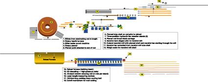
A handful of mills in the Western Hemisphere currently use the floating mandrel mill process. These mills comprise primarily seven interconnected production units (see Figure 1):
1. Rotary furnace
2. Billet centering machine
3. Rotary piercer
4. Floating mandrel mill
5. Reheat furnace
6. Stretch mill
7. Cut-to-length equipment
This inline process starts off with an as-cast round billet produced from ladle-refined steel originating from either a basic oxygen furnace (BOF) or electric arc furnace (EAF) melting process. The billet, which generally is cut to a specific length to produce a given length of finished product, is charged into a rotary hearth furnace. The billet is preheated to a rolling temperature of about 2,250 degrees F.
These cut billets are positioned on a loading dock and are separated by heat and customer order. Billets are indexed individually onto a chain conveyor for transfer to the rotary furnace. At the entrance of the rotary furnace, a peel, or mechanical jaw, picks up each billet and puts it into the furnace. The hearth rotates to receive the next billet. In like fashion, a peel enters the furnace, picks up a hot billet, and drops it onto a transfer table to be conveyed to the billet centering machine.
After the billet is discharged from the furnace, a small hole is punched into its end. This indentation acts as a starting point to aid in rotary piercing. This indentation is about 1 inch and aids in centering the piercer point tooling during the actual creation of the tube form.
Rotary piercing is a very fast and dynamic rolling process that produces a tube shell in just a few seconds. The process cross rolls the preheated billet between two barrel-shaped rolls at a high speed. The cross rolling causes high tensile stresses at the center of the billet.
The design of the piercer rolls causes the metal to flow along the roll and over a piercer point as it exits the process. The piercer point is a high-temperature, water-cooled alloy tool designed to allow the metal to flow over it as a tube shell forms from the rotary process. The piercer point is attached to a rod, which retains the point in place during the piercing.
The piercer point and rod positions are controlled by five idling bar steadier stands and thrust block that permit these tools to rotate by friction. Once the pierced shell is produced, the point and rod are retracted out of the shell, which immediately transfers to the second rolling process—the floating mandrel mill.
The floating mandrel mill comprises eight rolling stands using 16 rolls and a set of mandrel bars. These high-temperature, preheated alloy mandrel bars (made of T5 chrome, for example) are about 65 feet long and lubricated with a graphite-based compound. They are inserted into the pierced shell and then conveyed into the mandrel mill and rolled into an intermediate-size tube shell.
The graphite lubricant provides an interface between the shell and mandrel bar (tool) and facilitates bar removal. The mechanism of rolling the tube through the mandrel mill with the mandrel bar inside acts as a control to create an intermediate standard outside diameter (OD) and a controlled wall thickness, based on the resultant dimension of the mandrel bar set.
After progressing through the mandrel mill, the mandrel bar must be removed from the cooling mandrel tube shell. A bed chain engages and extracts the bar. The bar is returned to the mandrel mill for another shell after being cooled in a water bath. Generally, 10 to 12 mandrel bars are used in the cycle for the mandrel mill rolling system.
As the mandrel mill tube shell progresses toward the next step, it is weighed and measured by laser. This data feeds into the computerized process control system and modifies stretch mill processing for optimum gauge control.
The mandrel mill shell now must be reheated so that it can complete the final rolling process and gain its final dimensions and microstructural qualities. The tube enters a gas-fired reheat walking beam furnace and is reheated to a rolling temperature of 1,850 degrees F.
Upon exit from the reheat furnace, the tube receives a high-pressure water descale, removing the iron oxide scale that formed in the reheat furnace. A clean, scale-free surface is critical for good surface quality.
The 18-stand stretch mill is equipped with technology for gauge control and maximization of yield (minimal crop losses). As the tube exits the last stand of the mill, its length is measured by laser.
After inline measurement, the tube is transferred onto a 150-foot-long walking beam cooling bed. The tubes are allowed to cool in air and are rotated at every cycle to promote straightness and uniform cooling. The tooling requirements are considerable, with significant inventories of mandrel bars, mandrel mill, and stretch mill rolls and associated cassettes or mill housings.
Each of the stretch mill roll housings contains three rolls configured and positioned to create a round shape. These housings are changed out in series when size changes are called for in the operations. A typical OD change takes just less than 20 minutes.
The digital drive technologies currently available make possible incorporating the computerized control of stretch parameters to optimize tube product yield. Computerized tracking control of each mandrel mill tube shell with respect to its individual weight and length before entering the reheat furnace is used to modify stretch mill settings for each tube automatically.
The tubes then are conveyed to the cutoff mechanism, where they are cut to the prescribed length. Tubes are bundled and directed to subsequent finishing operations.
The unique features of this process are twofold. First, the process results in a seamless tube, homogenous in microstructure and physical properties throughout its OD and wall thickness. Second, this process is designed for high production of standard products typically used in the oil and gas industries.
This process can produce a variety of tubular products. Primary products include oil and gas production tubing/casing, drill pipe, line pipe, coupling stock, and standard pipe.
This process is not appropriate for producing specialty shapes or profile configurations other than round or circular. Any consideration of this would be a separate design and production process.

The Tube and Pipe Journal became the first magazine dedicated to serving the metal tube and pipe industry in 1990. Today, it remains the only North American publication devoted to this industry, and it has become the most trusted source of information for tube and pipe professionals.
start your free subscription
Easily access valuable industry resources now with full access to the digital edition of The Fabricator.

Easily access valuable industry resources now with full access to the digital edition of The Welder.

Easily access valuable industry resources now with full access to the digital edition of The Tube and Pipe Journal.

Easily access valuable industry resources now with full access to the digital edition of The Fabricator en Español.
In this episode of The Fabricator Podcast, Caleb Chamberlain, co-founder and CEO of OSH Cut, discusses his company’s...


