


Quality control for tube, pipe producers
Visual, thermal, laser inspection devices monitor processes, help prevent flaws
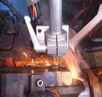
A thermal sensor positioned just after the weld point provides real-time monitoring of the weld profile. Image courtesy of Invisual E.
If you produce welded tube or pipe for a living, you know that tube and pipe mills need constant monitoring. Many variables are at play, such as the dimensions, hardness, and edge condition of the incoming material; the power delivered to the welding unit; and the condition of the mill as the tooling surfaces, bearings, and other components wear.
How does such a dynamic process result in a usable product? Even if you eliminate many of the potential problems by following a regular maintenance schedule and using standardized setup procedures, it can be a challenge. Forge welding, the process on electric resistance welding (ERW) mills, has different challenges from those in autogenous welding, the process used on plasma, laser, and tungsten inert gas (TIG) mills, but on both mill types, good or bad tube happens where the welding process takes place.
“Great yield results from two factors only—sound welds and stretch,” said Bud Graham, president of Welded Tube Pros LLC in Doylestown, Ohio. “In the past the shape of the formed pipe section was relatively unimportant. It didn’t have to be round at the weld point. The important points were parallel edges and the smallest possible deviation in edge height,” he said. The two processes, forge welds made with heat and pressure ERW mills and heat alone to make a cast weld structure on other mills—relied on rigid mill stands and shafts to maintain the outer profile and stretching to eliminate camber and edge wave.
“These principles haven’t changed, but these days tube and pipe manufacturers put much more emphasis on forming the product round—they want to eliminate any hint of ovality,” Graham said. “This is driven by the mandate to use the least possible amount of weld power so only the edges of the material are heated for welding. On the surface, this makes sense, but it doesn’t take into account that induction welding isn’t too efficient in the first place.”
Meanwhile, forming the tube or pipe round these days is more challenging as many mills operate with fewer fin and sizing passes. It’s all the more difficult because over the years line speeds have increased and mill staffing levels have decreased, Graham explained. Also, the price of steel is a big factor that has caused some operations to try to produce tube with narrower strip width than previously (see Sizing and Stretching sidebar).
“The need to reduce part weight, especially in the automotive sector, is driving the increased use of higher-strength, thinner-gauge material,” said Pierre Huot, founder and CEO of Invisual E. Inc., Toronto. “These materials are more challenging to form and weld than traditional materials,” he said.
The upshot is that you’re playing the hand you were dealt: you are trying to form round tube with fewer forming stands than in the past; the strip might be a little narrower than specified; line speeds have increased; some of the materials are more challenging to form; and staffing levels have fallen. If you’re accustomed to using an eddy current system or ultrasonic monitoring system, which are useful for detecting short-duration and long, continuous changes in the weld, respectively, you probably need more tools.
“It’s not enough to have a single method of monitoring the mill,” Graham said. “You have many more choices today. You can combine eddy current or ultrasonic with something else, such as a flux leakage detector, optical sensors, or laser-based detectors. This gives much better coverage—the whole is greater than the sum of the parts.”
Such equipment has other important benefits.
“Many tube and pipe producers are looking for ways to make their staff more useful and more capable,” Huot said. “They’re looking to automate more tasks, so the operators use less brawn and more brain.”
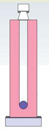
Figure 1: In an optical system, an emitter and a sensor are placed on opposite sides of the material to be monitored. Light from the emitter’s light-emitting diodes (LEDs) strikes the camera; the image is fed to a processor that determines the precise location of the material’s edge. The LEDs fire in series at a scan rate of up to 2,000 inches per second. Two of these setups can be used to measure the width of the incoming skelp, one unit placed at each edge. Image courtesy of Welded Tube Pros LLC.
It’s not just a matter of making a better product or reducing scrap. Many modern inspection devices are also helpful in setting up a mill after a switch to a different product, and even tuning the mill after a coil changeout for the same product, said Cornelius Sawatzky, sales manager for Xiris Automation Inc., Toronto.
Optics and Lasers
Monitoring locations, dimensions, and spatial relationships is usually done by either an optical system or a laser-based system. Optical systems rely on scanning light-emitting diodes (LEDs) to provide the light, a camera to capture it, and a processor to turn the image received by the camera into useful information (see Figure 1 and Figure 2). A laser-based system uses a laser emitter, receiver, and processor to do essentially the same thing. Of the two types, optical systems are a little more forgiving in their use—they don’t require quite as much care in aiming because the light spreads more. The accuracy is respectable, usually ± 0.010 in. Laser systems require more careful aiming and maintenance, but the upside is they are accurate to less than 0.002 in.
Despite such high resolution, it’s not possible to guarantee that the receiver or detector will find every defect. The limit of a system’s ability to detect flaws is determined by a combination of three factors: flaw size, mill speed, and the receiver’s shutter rate (number of images captured per second).
“Scanning LED systems were developed for use in steel mills,” Graham said. “That’s a harsh environment—scanning LED systems can accommodate mist, fog, and particulates if a clean air stream is blown across the emitter. A laser system is less forgiving and requires more care to ensure that the equipment is installed, aimed, and maintained correctly. With proper care, both systems work in steel mills, so they can work in a tube or pipe mill too.”
Sawatzky said that proper setup requires cooperation among the mill operator and the QA/QC staff or a production supervisor to determine the tolerances. After that, mill operators are capable of running the system.
What to Monitor
Optical systems and laser-based systems are used to detect or measure a variety of flaws in the strip of raw material (properly known as a skelp or slit mult) before it is welded and in the tube or pipe after it is welded.
Skelp shape and edge condition can be measured by an optical system in real time. You should keep in mind that the original coil varies in thickness; it’s thicker in the middle than at the edges. Therefore, two mults slit from the same coil can have different thicknesses. Furthermore, the slitting process cold-works the material, changing its hardness; this also can introduce changes in the material’s flatness. Two flatness defects are camber (a convex shape) and edge wave (a gentle ripple), which are the conditions you want to monitor.
The slitting process also results in a shear zone and a break zone that run the length of the slit mult. This isn’t necessarily a defect, but you should be aware that the slitter tooling dulls as it is used, so the edge quality varies from one end of the mult to the other; shear zone shrinks and the break zone grows as the blade dulls. Likewise, burrs are more likely to develop as the slitter tooling wears. Finally, the shear angle should be 90 degrees, but this also varies.
An increase in the amount of edge wave alerts you to take some action, such as adjusting the stretch squeeze pressure or increasing the weld heat. It might also indicate an upstream problem. Perhaps the slitter blades are due for sharpening, whether the product is slit in-house or supplied by a vendor.
The specifics of your mill arrangement—tools, setup, and the number of fin passes—determine the mill’s ability to accommodate excessive camber or edge wave. Knowing this condition exists, and its severity, allows you to make production far more predictable.
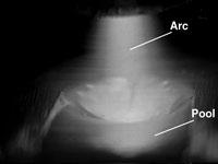
Figure 4: The arc and weld pool on a plasma mill are easy to see in this photograph, even though the arc is an order of magnitude brighter than the weld pool. Image courtesy of Xiris Automation Inc.
Strip width and edge condition can be monitored by optical or laser equipment. Rolled-over edges or improper edge break results in nonuniform forge conditions.
Edge mismatch warrants quite a bit of attention because edge presentation is the last step before heat and pressure create the forge weld in ERW operations. The visual output provided by a camera and precise measurements of a laser are a powerful combination for monitoring edge mismatch. Xiris and Invisual E use triangulation for an accurate measurement.
“The display shows the surface shape,” Sawatzky said. “It’s not the entire cross section, but just the top portion, so you can see how the right and left edges line up. The system overlays a perfect circle so you have a reference, and it measures the amount of mismatch as well.”
The operator can set limits, but doesn’t have to do any calculations—the limits are set to percentages of wall thickness.
Strip surface speed and the finished product’s exit speed can be monitored by contact encoders or laser Doppler gauges. The difference between the input and output surface speed helps you determine the amount of stretch, one of the key components in a good yield.
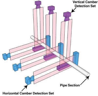
Tube straightness and roundness can be monitored in real time with optical sensors in two planes.
Looking at the Welding Arc, Pool, and Bead
Infrared systems and the associated software are sophisticated enough to monitor the thermal characteristics of the weld in real time. This type of system combines data streams for characteristics such as heat, pressure, and real maximum temperature to help the operator understand what is happening at the weld. The opticalless sensor collects thermal data at 400 Hz, processes the information, and looks for disturbances in the thermal profile (see lead photo and Figure 3).
Some mills have eliminated cold welds by working in tight tolerance envelopes and training the mill staff to adjust the mill and power inputs to the weld monitor procedure, Huot said.
Monitoring the weld area used to be limited to watching the arc only. Welding generates so much light that it overwhelms a regular camera; a dark lens filters much of the light, allowing you to watch the arc but obscuring the weld pool.
High dynamic range (HDR) cameras use sophisticated algorithms to tone down areas where the image is extremely bright so that the resulting image has consistency between the light and dark areas (see Figure 4). In other words, you can watch the size and shape of the arc and see what’s happening in the weld pool.
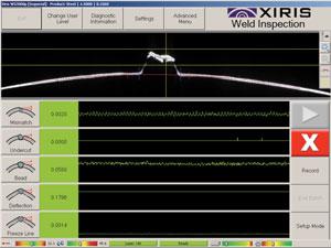
Figure 6: A graphic display that supplements numeric information with color indicators—red, yellow, and green are common—allows quick assessments. Image courtesy of Xiris Automation Inc.
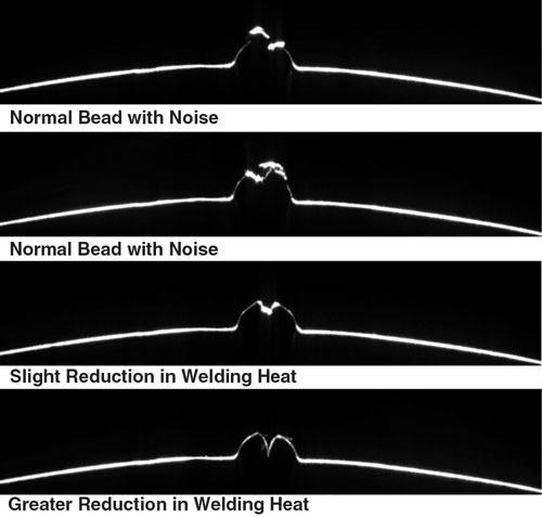
The outcome of the welding arc and the squeeze pressure is the weld bead. Even though the weld bead is a small portion of the parent material, it tells a lot about the welding conditions. A normal forge weld results in a slightly protruding (convex) bead, which usually is removed by the scarfing tool (see Figure 5).
A sunken (concave) bead is a sign of trouble that usually is noticed when the tube or pipe is inspected; likewise, an M-shaped bead comes to the operator’s attention when the scarfing station generates a split scarf. Laser-based monitoring of the bead shape at the weld station alerts the operator immediately that he needs to adjust the squeeze pressure or change the amount of weld current to deal with these problems.
Monitors and Alarms
Mill operators are too busy to stare at a monitor, attempting to decipher a complex display and trying to interpret its meaning, Huot said. Modern displays are intended to make the operator’s job as easy as possible (see Figure 6 and Figure 7).
“The systems generate a huge stream of data and sophisticated algorithms to turn it into meaningful information, but the operators need something immediate, so we rely on visual indicators like sliders to show if the process is good, marginal, or critical,” Huot said.
“A good visual display makes it easy for the operator to understand how the system works,” Sawatzky concurred.
Light towers and audible alarms commonly are used to let you know that some aspect of the process has changed and it needs immediate attention. Today’s systems also can mark the pipe or tube with a bit of paint so it gets extra scrutiny from quality control personnel.
It’s important to remember that these systems don’t pinpoint specific problems; they provide warnings that the process is no longer stable.
“An alarm doesn’t necessarily mean you’re producing bad tube,” Sawatzky said. “It means you should have a look at this.”
Sawatzky added that the data can be stored, thereby providing auditing capability. A look back at stored data can be helpful when investigating a customer complaint about substandard product.
Huot pointed out that mill monitoring equipment isn’t a matter of one-size-fits-all. The system’s settings must be tailored to each mill.
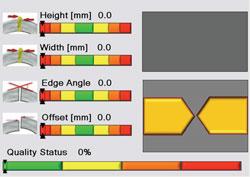
Figure 7: Visualization of the process’s health status allows the operator a quick view of current conditions to make decisions in real time. Image courtesy of Invisual E.
“The system is only as good as the people using it, and useful results come only after determining the correct threshold settings,” Huot said. “These systems need to be taught; determining the correct recipe or weld procedure is a learning process that takes time, but eventually the mill staff learns more about the process and quality procedures as a result.”
Standardized Setup Procedures
The last stage in setting up a mill is a destructive test, such as a reverse bend or cone expansion. Before getting to that stage, operators use less definitive test methods. For example, it’s common practice to check for mismatch by running a fingernail over the surface. This tells you that you have mismatch, but doesn’t measure it. In contrast, an electronic system measures the severity of edge mismatch.
“When trying to get the machine dialed in, instead of making some changes and then feeling for mismatch, or feeling for bead shape, this is much quicker,” Sawatzky said. “They look at the screen, make a little adjustment, and they can see the effect on-screen.
After that they take a cross-section sample to verify the setup, and they’re ready to go. It really simplifies the process and eliminates time-consuming trial-and-error adjustments,” he said.
Sizing and Stretching
Welded Tube Pros’ Bud Graham explained how ERW mills process a strip of material to make a good profile for welding. The most misunderstood subprocesses are two related aspects, sizing and stretching.
“A common misperception is that you can save money by decreasing strip width,” he said. “You might get by with a slightly narrower width than specified, but the forge welding process needs a little extra material. The forge welding process squeezes out this material, which otherwise would interfere with a sound weld. A strip that is too narrow reduces the amount of squeeze-out, making a sound weld difficult to achieve.”
Even if the weld is good, undersized strip generally results in smaller-than-desirable tube girth at the exit of the weld point. The tube doesn’t fill the sizing passes, resulting in less sellable footage.
Another critical, and often ignored, point is that the mill stretches the material, Graham explained. The mill’s driven rolls pull the material through the mill, stretching it in the process. This reduces ripples and waves in the incoming strip and straightens the tube after it’s welded. When the strip is the correct size, it fills the sizing passes, enabling the mill to put enough tension on the strip to stretch it. Undersized strip doesn’t do this, increasing the final product’s ovality and decreasing its straightness.
Slightly oversized strip doesn’t cause these problems. It actually increases the yield because the extra material gets pulled through the mill and increases the output. Rather than try to save a few dollars by buying undersized strip, tube and pipe producers should minimize gauge variation. Heavier-than-specified gauge results in heavier-than-specified wall thickness, which is a waste of material.
About the Author

About the Publication

subscribe now

The Tube and Pipe Journal became the first magazine dedicated to serving the metal tube and pipe industry in 1990. Today, it remains the only North American publication devoted to this industry, and it has become the most trusted source of information for tube and pipe professionals.
start your free subscription- Stay connected from anywhere

Easily access valuable industry resources now with full access to the digital edition of The Fabricator.

Easily access valuable industry resources now with full access to the digital edition of The Welder.

Easily access valuable industry resources now with full access to the digital edition of The Tube and Pipe Journal.

Easily access valuable industry resources now with full access to the digital edition of The Fabricator en Español.
- Podcasting

In this episode of The Fabricator Podcast, Caleb Chamberlain, co-founder and CEO of OSH Cut, discusses his company’s...
- Trending Articles
1
3D laser tube cutting system available in 3, 4, or 5 kW

2
Corrosion-inhibiting coating can be peeled off after use

3
Zekelman Industries to invest $120 million in Arkansas expansion

4
Brushless copper tubing cutter adjusts to ODs up to 2-1/8 in.

5
HGG Profiling Equipment names area sales manager
