


Contributing Writer
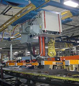 |
| Figure 1 |
Editor's Note: Occasionally, thefabricator.com will publish brief features that highlight the successful use of a specific product to solve a shop floor problem. The article's intent is to provide the reader a real-world application/solution story that could inspire efficiency improvements in production operations.
Moving finished tube and pipe products from mill runoff tables to the dunnage has been, and for the most part, remains dangerous and labor-intensive work.
Most mills are unloaded by hand. This action is dangerous for the operators, who are forced to work in unergonomic positions at highly repetitive rates. The constant bending and straightening cause lower back strain and general muscle soreness.
Shoulders and arms also are subject to strain and injury because products must be placed in specific locations in the bunk, which often requires the operator to reach into the placement position while bent over. Less serious injuries to the hands also are common.
In typical mill unload stations, two or three operators transfer tube from the runoff table. One person rakes a tube to the end of the table, and others pick it up and place it in the bunk. Once again, dangerous and labor-intensive.
Approximately 12 years ago, a tube manufacturer was looking for a safer system, but was reluctant to go with an automatic system because of the cost and complexity involved. The system had to be able to handle the complete size range each mill could produce. It also had to be able to lift and carry one complete row (24 inches) of any material and transfer it to the dunnage bunk. Single-operator operation was desired.
The obvious answer was to use a magnetic tool. The proposed system required several electromagnets placed at equal distances along a support (tool) bar so that the tube's weight could be spread across the length of the tool bar. The magnets also had to be positioned so they would prevent peel-off caused by unsupported ends. Once these issues were addressed, how to mount the tool to achieve the required range of motion was considered.
The initial units used a fully articulated manipulator. The system was floor-mounted on a pedestal, and while it did provide necessary range of motion, it was somewhat awkward to use.
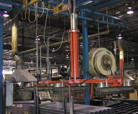 |
| Figure 2 |
The original system then was placed on an overhead I beam rail system (required because of the system's weight and moment loads). The manipulator platform was fitted with tractor drives controlled at the operator controls, which allowed loads to be transferred by pushing a button. While easy to use, the units were very heavy because of the number of magnets, tube load, power source, and battery backup systems. Operators still had to deal with the system mass during certain points in the process.
A complete study of how the operators were using the systems was conducted, and a new, lighter, and easier-to-use system was developed.
This next generation (see Figure 1) used a vertical-lift cylinder to control the up/down movement of the tool bar. The product now was carried centered on the lift device, which eliminated moment loading. The system was placed on less expensive light rail X-Y systems. While these modifications were a significant improvement over the earlier system, issues remained.
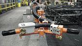 |
| Figure 3 |
Still looking for ways to make the system lighter and less complicated, designers scrutinized the magnet being used. Rare-earth permanent magnets that could be controlled pneumatically eliminated the need for the power source and battery backup systems. Electricity now was required for the tractor drives only. Eliminating these components reduced the system's weight and complexity.
The current generation (see Figure 2) can be mounted to either ceiling-hung or floor-supported X-Y rails. Runways can be any length with bridges up to 34 ft. The system incorporates tractor drives to move the bridges on the runways.
The manipulator platform location can be controlled manually or powered. However, because the tube generally is run in batch lengths, positioning is required infrequently. The manipulator is easy to relocate on the bridges, which makes tractor drives unnecessary.
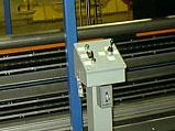 |
| Figure 4 |
Used in conjunction with a properly designed runoff table, these systems can be run by a single operator at one end of the tool bar who controls the up/down movement and loading/unloading by pushing buttons (see Figure 3). Or they can be run by remote control systems, such as an operator pedestal located at the mill controls (see Figure 4) or a full RF control.
The systems have gripper safety circuits to prevent unsupported loads from releasing if the release button is activated by accident.
Relying on automated systems for loading and unloading tube can allow operators to remain in ergonomically correct positions throughout the process and reduce strains and injuries.
Bill Brady is president of Nomax Solutions LLC, 1731 Southampton S.E.,Grand Rapids, MI 49508,616-248-5444, nomax@sbcglobal.net.

The Tube and Pipe Journal became the first magazine dedicated to serving the metal tube and pipe industry in 1990. Today, it remains the only North American publication devoted to this industry, and it has become the most trusted source of information for tube and pipe professionals.
start your free subscription
Easily access valuable industry resources now with full access to the digital edition of The Fabricator.

Easily access valuable industry resources now with full access to the digital edition of The Welder.

Easily access valuable industry resources now with full access to the digital edition of The Tube and Pipe Journal.

Easily access valuable industry resources now with full access to the digital edition of The Fabricator en Español.
In this episode of The Fabricator Podcast, Caleb Chamberlain, co-founder and CEO of OSH Cut, discusses his company’s...


