


Using FEM to compare tube forming processes
Analyzing residual strains, stresses
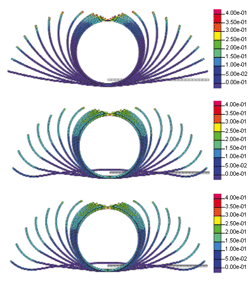
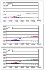
Three roll forming processes typically used in tube and pipe production are single-radius forming (top), edge forming (middle), and partial-step forming (bottom). FEA shows the displacement of material in each forming pass.
In tube manufacturing, product quality is a major concern, especially as it relates to the subsequent fabricating processes and the tube's end use. For example, will the tube be bent? To what extent? Will it be hydroformed? What will it be used for? A power boiler? A bicycle frame? An automotive engine cradle?
Knowing the final end use is crucial in determining how to manufacture the tube to make sure it has enough ductility to be fabricated successfully. Consistency in the characteristics is an important property; variations in the tube's mechanical properties, such as material strain, yield stress, and hardness, can lead to product failure.
Many tube manufacturers use the same processes they used for many years because they work. Tube tends to be a commodity, the profit margins are slim, and few in this industry want to make changes (take risks) that could disrupt the manufacturing process. The manufacturing manager, setup personnel, and mill operators often are unwilling to accommodate changes in the design or setup that will bring something new into the process. In many cases, they worry that a change will cause problems that they don't have the experience to solve. Sometimes they simply refuse to make any changes from their existing design or process without considering the possible advantages of the modified design.
Many strategies can result in better tubes: using different forming designs, changing the forming sequences, modifying the tube mill, and changing the feedstock.
Despite such efforts, many in this industry are lacking in-depth knowledge regarding what happens inside the tube structure and the amount of strains and stresses that occur during the manufacturing process. R&D to determine whether the forming process commonly used is suitable for the forming mill and product applications is lacking. Finite element method (FEM) software, especially programs designed specifically for roll forming, opens up possibilities to examine more accurately the traditional tube forming methods and enable design engineers to improve the tube manufacturing process.
Finite element analysis divides the strip into a large number of small squares, or bricks, to determine how the forming forces affect the entire strip.
Innovation in forming design results in less energy consumption, easier and more repeatable setup, reduced material consumption, faster mill speeds, better tube quality, and a higher level of customer satisfaction. Long-term advantages are lower costs and an improved reputation. Ignoring technology advancements means missing these potential benefits and falling behind as the industry advances.
Tube Manufacturing Processes Simulated
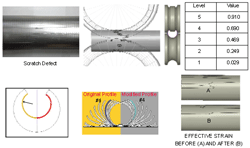
In addition to determining the general characteristics of the forming process, FEA can analyze small defects such as surface scratches. It also it useful in finding the specific cause and a cure. In this case, the cause was an effective strain rate that approached 1. Modifying the side roll radius of the tooling at station #4 eliminated the scratch.
Numerous computer simulation tools are available for forging and stamping processes, and these tools' effectiveness is proven. However, when it comes to the roll forming process, the choices are limited, and some users' questions are not yet answered.
Roll forming is significantly more complicated to simulate than forging or stamping. Roll forming consists of several roll stands that are connected sequentially, so the simulation time is longer than it is for other metal forming processes; in some cases, it is 10 times longer.
This study analyzed one FEA package that specializes in roll forming simulation. It investigated and compared the strains and yield stress values of different tube forming methods to see if one particular forming method is better than the others.
The study's main objective was to investigate and compare the material behavior during the tube forming process and to determine which tube forming process results in the least residual strains and stresses. This is crucial for secondary operations such as hydroforming or bending.
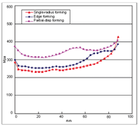
The initial strip width is 88.59 mm. Comparing the yield stress distribution along the center of the section at the end of the welding pass shows that single-radius forming tends to develop the highest yield stress throughout the section; partial-step forming shows the least stress across the section; and edge forming is between the other two. This relationship changes near the strip's edge, where partial-step forming's yield stress increases and surpasses that of the other two forming methods. Furthermore, the difference in strain at its lowest point and its highest point is greatest for partial-step forming.
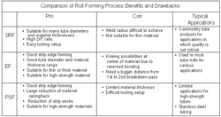
Three common roll flower designs are:
All tooling setups have four breakdown and three fin stations, with side rollers between them and before the welding station. After it is welded, the tube is sized to the final dimension with several pairs of sizing stations. Bd = Breakdown; Sr = Side Roll; F = fin pass; G = Guide Roll; W = Weldunit; S = Sizing pass; TH = Turk- Single-radius forming (SRF), also known as center-radius forming.
- Edge forming (EF) or modified edge forming, also known as W-forming.
- Partial-step forming (PSF), also known as versatile edge forming.
Single-radius Forming. In single-radius forming, the material is formed with a series of rolls having single-radius contours. The radius decreases progressively to approach that of the final closed section.
Edge Forming. In edge-radius forming, the material edges are formed to a radius close to the tube radius in the first couple of forming stations. Another variation of edge forming is W-forming, in which the first breakdown station forms the strip into a shape that resembles the letter W.
Partial-step Forming. In partial-step forming, the edge is formed into the radius, but unlike edge forming, in the first several forming stations material is taken increasingly from the center part to form the radius.
A total of 2,100 brick elements were used for each pass. All three simulations were performed only to the welding pass. The flow stress was defined by the following function with the given coefficients. In this equation, flow stress is a function of the strain only, not of the strain rate.
Finite element analysis reveals that the longitudinal strain distribution varies considerably from center to side. Single-radius forming (top) has the lowest difference: partial-step forming (bottom) produces the highest difference; and edge forming is between the other two (middle).
Where: K = 537
a0= 0.0126
a1= 1.0
b0= 1.0
b1= 0.0
Comparing the Simulation Results
A higher yield stress tended to limit the material's ductility and the effectiveness of subsequent forming operations such as bending and hydroforming. Minimizing yield stresses and distributing them throughout the cross section as evenly as possible made the tubular section more suitable for secondary operations. One of the well-known effects of the roll forming process is longitudinal strain. Uneven longitudinal strain distribution can result in defects such as bow and twist during and after the roll forming process.
Of the three designs, single-radius forming showed the least amount of yield stress except at the material edge near the welding pass, because that material is forced from a bigger radius to the welding radius.
Edge forming showed slightly higher yield stress than single-radius forming, but more even (homogenous) distribution throughout the tube cross section.
Surprisingly, partial-step forming showed much higher yield stress than the other two methods. The result of this particular example contradicts the industry assumption that partial-step forming results in a lower yield stress distribution compared with the edge forming method.
The distribution of longitudinal strain showed similar characteristics. Single-radius forming showed the smallest difference in longitudinal strain between the center and edge. Partial-step forming showed the greatest longitudinal strain difference.
Results of the Study
This study was a simple and quick analysis of the main tube design characteristics without going into a more detailed investigation of parameters such as:
- The effect of changing the incoming material quality.
- The effect of downhill forming when using one of these three forming methods.
- Increased or decreased station distances.
- Increasing the roll diameters.
- Running the mill at a higher speed.
- Other possible combinations and their effects.
This quick FEA shows that modern software technologies can give roll forming engineers and mill operators a useful tool to help them solve forming problems and improve the forming process by showing where and how to tweak the setup.
The results do not show conclusively which forming method—single-radius forming, edge forming, or partial-step forming—is best to achieve optimal tube products. The simulation shows that small changes on the mill and in the design alter the results, sometimes dramatically. Achieving a better result is a matter of simulating each forming method with its own parameters; however, this short study has shown that it is possible to improve and to find better tube forming methods by using the FEA software.
Another advantage is that knowing material properties and strain values of tubes will make further analysis with computer simulation tools in the secondary process more accurate.
This technology is becoming more accessible for industries because of better graphic user interface and more powerful computer hardware. Using it wisely can help a tube producer cut costs and become more competitive.
Dr. Naksoo Kim is a professor at Sogang University in Korea and CEO of SHAPE Co., #301 Daejin Building 468-3, Seokyo-dong, Mapo-gu, Seoul 121-842, Korea, 82-2-334-0560, shape@shape.co.kr, www.shape.co.kr.
Budi Francisco is director of roll forming at Roll Machining Technologies and Solutions (RMTS), 641 Forestwood Drive, Romeoville, IL 60446, 815-372-9100, bfrancisco@rollsolutions.com.
About the Author
About the Publication
subscribe now

The Tube and Pipe Journal became the first magazine dedicated to serving the metal tube and pipe industry in 1990. Today, it remains the only North American publication devoted to this industry, and it has become the most trusted source of information for tube and pipe professionals.
start your free subscription- Stay connected from anywhere

Easily access valuable industry resources now with full access to the digital edition of The Fabricator.

Easily access valuable industry resources now with full access to the digital edition of The Welder.

Easily access valuable industry resources now with full access to the digital edition of The Tube and Pipe Journal.

Easily access valuable industry resources now with full access to the digital edition of The Fabricator en Español.
- Podcasting

In this episode of The Fabricator Podcast, Caleb Chamberlain, co-founder and CEO of OSH Cut, discusses his company’s...
- Trending Articles
1
Zekelman Industries to invest $120 million in Arkansas expansion

2
3D laser tube cutting system available in 3, 4, or 5 kW

3
Corrosion-inhibiting coating can be peeled off after use

4
Brushless copper tubing cutter adjusts to ODs up to 2-1/8 in.

5
HGG Profiling Equipment names area sales manager
