


Project Engineer
 |
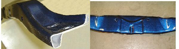
| Figure 1 |
Vehicle structures have evolved over the years in response to demands for improved performance, safety, cost reduction, and changes in technology. In today's automotive environment, those first three factors often are concurrent requirements, while the last can provide the opportunity to get there.
Tube hydroforming is indeed a change in metal forming technology that can provide benefits in each of the other categories-or all three-compared to welded assemblies of stampings. It has been accepted relatively quickly because of these merits.
Hydroforming seems to be preferred for a number of applications, such as radiator enclosures, engine cradles, instrument panel beams, and frame rails. Engineers continue to explore other applications to see where additional advantages may lie. Capitalizing on these may require re-evaluating the function of the structure rather than merely replacing tubelike welded assemblies with hydroformed tubes.
An example of such a new application is the 2002 Dodge Ram® front-end structural module (FESM). This assembly incorporates the radiator enclosure (which had been hydroformed from 1994 to 2001), but additionally extends rearward to the firewall. Thus it supports the fenders, hood, and other engine compartment components.
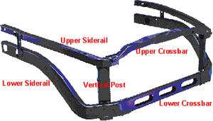
The FEMS includes eight hydroformed tubular parts and four small stampings. The components are partly assembled before they are shipped to the vehicle assembly plant. This means that the upper and lower side rails are welded together with a vertical post and two brackets to make a left and right subassembly. In the vehicle, assembly is completed by attaching lower and upper crossbars to the side subassemblies and other front-end components in logical sequence. The frame rails attach to the brackets under the vertical posts. Shipping efficiency and ease of handling also are improved by this approach.
Weight is reduced by 26.5 kilograms (57 lbs.), mainly because of the tubing's inherent closed cross sections and the lack of weld flanges. All parts use galvanneal mild steel electric resistance-welded (ERW) tubing for the desired balance of corrosion resistance and economy. Tube sizes range from 57 to 92 mm with wall thicknesses from 1.3 to 1.7 mm. Strength, rigidity, and airflow all were increased substantially compared to the stamped and welded assembly in the previous version of this truck.
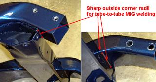
The side subassemblies use tube-to-stamping and, more unusually, tube-to-tube welding (see Figure 1). This reduces stamping content and, more important, the number of assembly steps and cost. The hydroformed tube surface position repeatability is conducive to stable robotic welding.
 |
| Figure 2 |
The four side rails and upper crossbar must be bent before hydroforming. The upper crossbar and lower side rails also must be preformed in areas where the final cross section is tall and narrow in the die travel direction.
Each of the tubes is formed with the pressure sequence hydroforming (PSH) process. This allows forming of complex-shaped parts with relatively low-tonnage hydroforming equipment with shorter cycle times. Floor-to-floor cycle times range from 20 to 25 seconds. Maximum pressure used is less than 7,000 PSI.
 |
| Figure 3 |
General Observations. There are a total of 157 holes in this assembly, of which 149 are punched simultaneously in each of the hydroforming dies. This method is used to take advantage of superior dimensional stability, as well as lower capital and piece costs, compared to the common alternative of using laser-trimming cells. Additionally, some holes-including extrusions-can be done only in the hydroforming die.
A variety of hole styles and sizes are evident in Figures 1, 2, 3, and 4. They may be pierced to fit measurement gauges, extruded to accept self-threading fasteners, or pierced with hex-shaped holes for installing fastening and other types of nuts. It is normal that slugs cut from the holes are left attached to prevent problems in the hydroforming die and the vehicle.
The ability to achieve a high hole count is directly related to using lower forming pressure. Higher internal pressure levels cause higher stress, which requires the die to be stronger. The size of a particular punch unit also must be bigger to overcome the internal pressure.
 |
| Figure 4 |
Adding punch units to the die weakens it. However, die strength can be substantially lower when using low forming pressure because there is little risk of overstressing and cracking the tool. This provides the opportunity for more densely packed punch units.
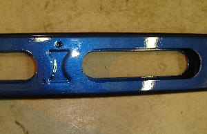
Special Notes. The size of the holes ranges from 5 mm round to the 52- by 201-mm oval-shaped holes shown in Figure 4. One item of note is that six of the latter holes are pierced in one part that is about 1 m long (see Figure 2). They are outpierced when the fluid pressure inside the tube shearing the metal against the sharpened die edge.
As a consequence of outpiercing, the slugs cannot remain attached to the part and are removed from the die. This technique was developed as a less costly alternative to plasma or laser cutting. Total cut length for these six holes is 2.77 m. Several much smaller holes are pierced concurrently. The method met the design requirement, but is not limited to what was done in the Dodge project.
 |
| Figure 5 |
The main reasons for creating these large holes are increased airflow and reduced part weight with an eye toward retaining much of the structural strength and rigidity in the remaining part of the cross section.
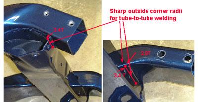
Surface complexity of a part can serve several purposes, as shown in Figure 1 and Figure 5.
Figure 1 shows the front of the side subassemblies. The mating pieces require relatively sharp corners to facilitate tube-to-tube welding. The measurements are shown as a multiple of the wall thickness T on the outside surface.
The pictures in Figure 5 show the upper crossbar end and center sections of the front assembly. The end on the left is formed to a near wall-to-wall condition for solid mounting. The center section shown on the right displays pockets formed to fit the hood latch bracket.
In this application, the combination of the functional requirements of this FESM and the design flexibility of hydroforming resulted in an assembly comprising a high percentage of hydroformed tubing and a low percentage of stamped brackets. It represents a new structural solution to an old problem-that of providing a strong and cost-effective skeleton for the components of the vehicle's front end.


The Tube and Pipe Journal became the first magazine dedicated to serving the metal tube and pipe industry in 1990. Today, it remains the only North American publication devoted to this industry, and it has become the most trusted source of information for tube and pipe professionals.
start your free subscription
Easily access valuable industry resources now with full access to the digital edition of The Fabricator.

Easily access valuable industry resources now with full access to the digital edition of The Welder.

Easily access valuable industry resources now with full access to the digital edition of The Tube and Pipe Journal.

Easily access valuable industry resources now with full access to the digital edition of The Fabricator en Español.
In this episode of The Fabricator Podcast, Caleb Chamberlain, co-founder and CEO of OSH Cut, discusses his company’s...


