


Contributing Writer
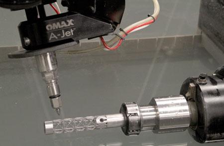
Figure 1: A Standard 2-D AWJ System Retrofit for 3-D Applications.
Abrasive waterjet (AWJ) cutting systems now are being equipped with accessories and control software that enable them to move beyond traditional 2-D shapes to more complex 3-D and cylindrical shapes. Also available are easy-to-program systems for cutting relatively complex pipe intersections and saddles.
Articles I have written in the past have discussed the relative merits of the basic abrasive waterjet cutting process. A cold-cutting process suitable for almost any material, waterjet cutting has the unique characteristic of not altering in any way the properties of the material being cut. This makes it ideal for making stress-free cuts in metal components that will become part of a weldment.
The challenge in making accurate parts with this process traditionally has been associated with the fact that the jet bends as it cuts through the material, which leads to the potential for undercutting and consequent inaccuracy in corners and curves. However, modern, PC-based control systems with sophisticated computer modeling of jet behavior have been developed to adjust for the bending jet stream and eliminate this issue automatically by moving in five axes.
With these modern control systems and precise cutting tables, you can easily make flat parts to accuracies within a few thousandths of an inch; all motion programming for the five axes is done automatically directly from a standard 2-D CAD drawing file. However, these simple-to-program systems generally have been limited to flat 2-D inputs.
Today much mechanical design work is done directly in 3-D. Accordingly, AWJ cutting systems have now entered the 3-D arena with hardware accessories and control software that greatly expand the capability of 2-D cutting tables and thus the range of applications for these systems.
Programmable Z axes permit cutting parts with vertical contour. Articulating cutting heads permit cutting of beveled surfaces. Programmable rotary axes allow cutting of cylindrical surfaces and components. Figure 1 shows a standard 2-D AWJ system that has been retrofitted with all three of these features.
The rotary-axis accessory is particularly noteworthy because of the basic design challenge of creating a precise rotating actuator capable of holding a variety of raw material stock and maintaining accuracy over a long life in an absolutely miserable environment—submerged in a mix of water and fine abrasive particles. Advanced materials and rotary seal technology keep the abrasive-laden fluid outside of the sealed rotating components, and a universal rotary mount accepts many gripping mechanisms and fixtures for holding material stock. Long parts can be accommodated through the use of a “steady rest” holder and the free end of the stock.
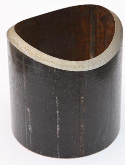
Several advanced programming systems are available for use with the rotary axis. The first is for parts or features that can be visualized as flat shapes “wrapped” around a cylinder. An example of such a shape can be seen in Figure 2. For this system, the programmer or operator creates or imports a simple 2-D CAD drawing of the desired shape and simply specifies the axis orientation and radius dimension of the cylinder it is to be wrapped around. The basic cutting parameters such as material, thickness, and desired cut quality then are entered into the control software, and the controller fully programs the desired tool path and cutting speeds.
Figure 1 shows an example of this process in action. The material stock has been clamped into the rotary-axis unit, which is oriented parallel to the x-axis of the cutting table. The control computer has converted the x and y coordinates of every element of the flat shape into x and r-theta coordinates (where r is the radius of the cylinder and theta is the angle of rotation of the rotary axis) of the desired cylindrical shape. The resulting series of motion commands is then transmitted to the x and theta actuators as the part is made.
The relatively complex contours required for cutting pipe intersections or saddles call for a different programming approach. Determining the desired cut pattern on a case-by-case basis is complex and time-consuming. Simultaneously creating a weld-prep bevel in the contour being cut—as is often the case—is even more difficult. Consequently, a preprogrammed parametric shape generator has been developed for these types of applications.
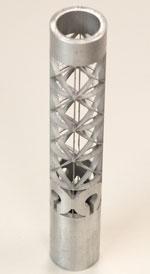
Figure 2: Example of a “Wrapped” Cylindrical Part.
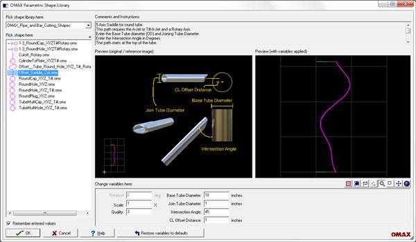
You enter the diameters of the two pieces of pipe, the desired angle of intersection, and the desired bevel angle in the software, as shown in Figure 3. The parametric shape generator then automatically determines the geometry and creates values for X-axis linear location, rotary-axis angle, and articulated-head angle for every location along the desired tool path. Once this is determined, you then enter the usual material, thickness, and cut quality values and the system programs itself to make the part. This same system can also be used for creating bevel cuts on pipe ends, as seen in Figure 4.
When cutting cylindrical parts, you must be aware of a few key issues. For one, the basic through-cutting nature of the AWJ process must be accounted for. Once the waterjet has cut through the upper surface of the cylinder, it has the tendency to cut right on through the back surface as well. The can be addressed by the use of a hard deflector placed inside the tubing stock to deflect the jet down the tube axis. This tendency also can be mitigated simply by reducing the power of the abrasive waterjet with a smaller nozzle and/or reduced water pressure.
A second potential issue is that because of the geometry of a cut cylindrical part, the part can become trapped in the cylinder it has been cut from. An excellent example of this is the titanium link necklace shown in Figure 5. What started as a rigid, small-diameter tube of titanium has been converted to a flexible necklace with interlocking parts that cannot be separated.
Finally, many 3-D programming systems have posts that produce input files directly to AWJ cutting machines with up to six axes of motion. These systems generally are much more complex than the systems described here and have a steep learning curve. But for those shops already using such software, the posts simplify waterjet operation.
The 3-D capabilities that have been discussed expand the range of applications for AWJ cutting systems. A shop or factory can add 3-D capabilities by retrofitting the hardware and software can be retrofitted to its existing standard 2-D AWJ cutting table. These expanded applications point toward continued growth and development in AWJ technology and further growth and profitability for AWJ users.
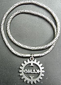
Figure 5: Titanium Link Necklace.


The Fabricator is North America's leading magazine for the metal forming and fabricating industry. The magazine delivers the news, technical articles, and case histories that enable fabricators to do their jobs more efficiently. The Fabricator has served the industry since 1970.
start your free subscription
Easily access valuable industry resources now with full access to the digital edition of The Fabricator.

Easily access valuable industry resources now with full access to the digital edition of The Welder.

Easily access valuable industry resources now with full access to the digital edition of The Tube and Pipe Journal.

Easily access valuable industry resources now with full access to the digital edition of The Fabricator en Español.
In this episode of The Fabricator Podcast, Caleb Chamberlain, co-founder and CEO of OSH Cut, discusses his company’s...


