


Contributing Writer
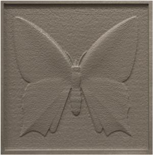
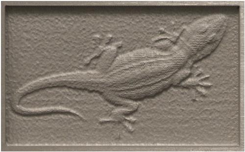
Figure 1: A 3-D image made with an abrasive waterjet.
Abrasive waterjet (AWJ) cutting is performed with a stream of very fast-moving abrasive particles that are not easily deflected or stopped. As a result, AWJ cutting generally is considered a through-cutting technology that is not well-suited to controlled-depth material removal. However, as ongoing research has improved our knowledge of jet behavior and our ability to create computer models of that behavior, it has become possible to use the AWJ process to create relatively complex and subtle 3-D images (Figure 1). Moreover, advanced control software now permits a fabricator to make such images with relative ease. How is it done, and how can this capability be used?
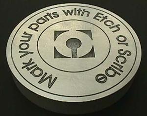
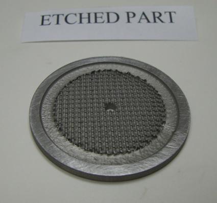
Simple AWJ etching, as shown in Figure 2, has been understood for a long time. The basic concept is to move the cutting nozzle at a traverse speed faster than its maximum cutting speed, so that the abrasive stream simply does not have the time needed to cut completely through the material. This results in the abrasive stream cutting a groove in the material, rather than a full through-cut.
The depth of the groove depends on nozzle power, material properties, and the traverse speed. A slower speed creates a deeper cut. Softer material, or softer regions of a nonuniform material, also means a deeper cut.
Using relatively low power at the cutting nozzle (typically by using a reduced water pressure and a reduced abrasive flow rate) lowers the required traverse speed and provides better depth control. Low nozzle power also helps keep cutting depth variations, which occur as the nozzle has to slow for corners and bends, at an acceptable level.
Such AWJ etching is widely used for applications such as tool marking and part identification, but it certainly does not show the subtlety of the image in Figure 1.
Considerable research has been dedicated to fully understanding the operating characteristics of an AWJ stream and to creating and improving computer models of that behavior. Thus, it is now possible to predict fairly accurately the etching depth for a given set of nozzle and material parameters as a function of traverse speed.
At the same time, advanced linear-motion systems have been developed that permit very smooth and accurate control of traverse speed, and also permit very subtle yet rapid changes in speed along a tool path. The end result is that a traverse speed profile can be programmed accurately and predictably to vary etching depth along the path of the nozzle. By creating a tool path that is simply a series of closely spaced parallel lines back and forth across a defined area, and by varying the tool traverse speed so that some areas are etched deeper than others, fabricators can create a 3-D pattern or image.
Of course, programming such a variable-speed tool path by traditional manual methods would be incredibly time-consuming. A modern PC controller automates the process as follows:
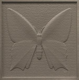
The result is a 3-D image taken directly from a photo or high-contrast drawing file. Such an image can be etched into a larger piece of material as part of an overall design (Figure 6) or completely cut around its perimeter to become a stand-alone piece (Figure 7).
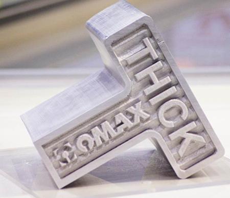
To date, most of the applications of this 3-D image capability have been in the worlds of art and architecture and include such things as stand-alone art pieces, decorative panels, and textured surfaces for floors and walls. However, we are beginning to see applications suitable for machine shops and fabricating shops, such as the textured gripper shown in Figure 8, or the deeply etched logo shown in Figure 9. In a sense, 3-D AWJ imaging is in the same place that AWJ cutting was 20 years ago—an interesting technology looking for applications. It is reasonable to assume that those applications will come from the same place they did 20 years ago—you, the readers of this article.
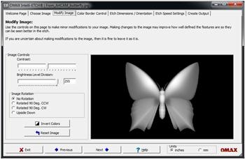
Figure 4: Software used to enhance desired 3-D image


The Fabricator is North America's leading magazine for the metal forming and fabricating industry. The magazine delivers the news, technical articles, and case histories that enable fabricators to do their jobs more efficiently. The Fabricator has served the industry since 1970.
start your free subscription
Easily access valuable industry resources now with full access to the digital edition of The Fabricator.

Easily access valuable industry resources now with full access to the digital edition of The Welder.

Easily access valuable industry resources now with full access to the digital edition of The Tube and Pipe Journal.

Easily access valuable industry resources now with full access to the digital edition of The Fabricator en Español.
In this episode of The Fabricator Podcast, Caleb Chamberlain, co-founder and CEO of OSH Cut, discusses his company’s...


