


Contributing Writer
Abrasive jets are used for machining many materials and parts. Workpieces that can be abrasive jet-machined range from glass artwork to high-precision stamping dies. No known fixture serves all applications.
Like most other machine tools, abrasive jet machines ship with only the minimum fixturing equipment necessary to get started. The fixtures required for most applications are easy to make with the abrasive jet machine itself. Some proven designs for such fixtures are presented here, and the reader is encouraged to use them in any combination for his particular work.
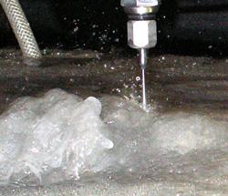 |
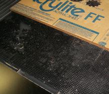
| Figure 1 The jet causes large disturbances that can move light, unsecured materials. |
Fixtures are needed to locate the workpiece relative to the coordinate axes of the machine and to keep it in place while the machining is in progress. Unwanted workpiece movement is the main source of error by new abrasive jet users.
Because tool forces are low—usually less than a few pounds—operators can be lulled into using little or no clamping. But there are other factors to consider. The jet drives a large quantity of air into the catcher tank below the work. This air rises and carries with it a large volume of water that easily can lift the workpiece and move it sideways (see Figure 1). This effect is troublesome, particularly for sheet metal less than 1/4 in. thick.
Small pieces of scrap may tilt up and snag on the nozzle as it passes over, which creates a significant side force. Finally, in underwater cutting, garnet often rises to the top of the plate, and the nozzle drags through it, causing side forces. All of these forces can move a poorly clamped workpiece during cutting.
Most abrasive jets are used for making flat parts from plate or sheet or for adding features to existing parts that are more or less flat. Larger parts are supported from below, and fixturing involves holding them on a support table parallel to the plane of the machine's X-Y axes. Small parts easily can be lost by falling through the support grid, and fixturing must compensate for this possibility. For all flat-part fixturing, three parameters must be set: the X position, the Y position, and the angle of rotation about the X-Y point.
For cutting parts from low-cost material, the plate usually is locked into position with low precision, and the entire part is made by first cutting internal holes and then cutting the part perimeter, which releases it from the plate. Whether the part is located precisely on the plate usually is of little importance. Location within 1/16 in. or even 1/4 in. often is sufficient.
When features are added to existing parts, fixturing becomes more critical, because the new features must be located precisely in relation to the other features on the part. Location within 0.005 in. or less often is required.
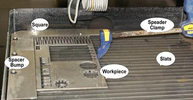 |
| Figure 2 A square and spreader clamp are commonly used for fixturing. |
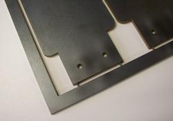
Plate or sheet stock usually is supported from below on slats (see Figure 2). During the waterjet operation, these slats get cut and eventually must be replaced. For economical reasons, the most common construction uses removable slats that can be replaced individually instead of replacing an entire slat assembly when one portion is worn. These removable slats offer support only in the vertical direction. Clamping to the slats does not provide reliable support against sideways motion.
A common method of locating a plate and providing side support is with a square. The square is cut from a plate bolted into the machine tank and then cut with the machine. This ensures that the square's edges are perfectly parallel with the machine's axes. The material to be cut then is wedged against the square with a spreader clamp as shown in Figure 2.
Tips for Using Squares. Several tips exist for successful square construction and use. First, the outer edge of the square can be made with three spacer bumps that locate against the sides of the tank or machine frame. These bumps locate the square so that it can be removed easily and reinstalled in the exact position.
Making a really long square is unnecessary. A second piece bolted far from the corner of the square can be cut at the same time as the square and used to locate a long plate. The square material should be no thicker than the material being cut to prevent the nozzle from breaking against the square. A small relief at the corner of the square prevents interference with sharp corners of the workpiece. The corner location can be set as a home position for easy reference to locations on the workpiece.
Next, clamps can be added to the square. These are useful for cases in which it is harmful to push on the material with a spreader clamp. For example, the scrap may become weak from the cuts and can deform or break, which causes motion, or perhaps the material must be cut completely in half.
 |
 |
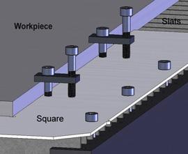
| Figure 3 Clamps can be added to the square. |
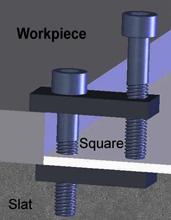
Figure 4 The clamp has parts above and below the square. |
Figure 3 shows clamps affixed to the square. The clamping screws are those nearest the workpiece. The screws farthest from the workpiece are used to adjust for various material thicknesses.
Figure 4 shows more clamp system detail. The top clamp contains a clearance hole for the clamp screw and a tapped hole for the adjusting screw. The hole in the square is a clearance hole. The bottom clamp contains a tapped hole for the clamp screw. The bottom clamp fits between slats, which prevent it from rotating. A thin layer of rubber on the clamping surface makes these clamps suitable for brittle materials like glass or ceramic tile.
Note that even when solidly clamped along the edges, a lightweight material can be lifted by the jet action shown in Figure 1. Placing steel weights on lightweight material helps prevent lifting.
 |
 |
| Figure 5 Parts held to the waste by tabs |
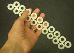
Figure 6 Parts held together by tabs |
Small parts can fall between the slats and become lost. Several strategies can prevent this. First, when cutting long, slender parts, cut them with the long direction perpendicular rather than parallel to the slats, so that they are supported by at least two slats. If the part is so small that it spans less than TWO slats in its longest direction, tab the part and cut or break the tab manually after cutting is completed. Figure 5 shows thin plate parts tabbed within the waste frame, and Figure 6 shows small plastic rings tabbed together rather than to the waste piece.
 |
 |
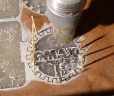
| Figure 7 Toothpicks wedge the part in place, preventing damage at the moment of separation. |
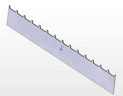
Figure 8 Modification of a slat to reduce reflected jet damage |
A small part that is not tabbed may move as the last part of the cut is finished and becomes loose. The part can be scarred if it moves into the jet.Figure 7 shows a method for wedging the part in place with toothpicks to prevent this damage.
Some materials are damaged by the jet reflecting off the slats and frosting or scarring the support surface. Several approaches can avert this damage. In some cases it is possible to cut with no slats beneath the part and retain the part with tabs, as mentioned previously.
The slats can be modified as shown in Figure 8 so that the likelihood of jet reflection is reduced.
A sacrificial material can be placed between the material and the slats to shield the work material from the reflected jet. Thin sheet metal, pressed board, and plywood are common sacrificial materials.
 |
 |
| Figure 9 A waterjet brick prevents reflected jet damage to Plexiglas®. |
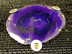
Figure 10 A geode is held in a waterjet brick with screws and washers. |
Another deterrent is a whole different support system referred to as a waterjet brick. A waterjet brick is corrugated plastic material often supplied in 4-in.-thick blocks with a cross section that measures 8 in. by 24 in. The brick can be placed on top of the slats or mounted so that it is flush with the slats as shown in Figure 9. Small workpieces can be fastened to the brick with screws and washers (see Figure 10). In this case, the brick must be fastened to the machine frame to prevent overall motion of the part and brick. The jet quickly damages the brick, as shown on the left side of Figure 9, and maintaining a brick cutting surface is more expensive than a slat system. Nevertheless, it is the support material of choice for some classes of work.
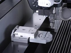 |
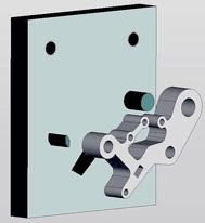
| Figure 11 Clamping fixture mounted on an EDM pallet |
Sometimes the task is to add more features to or trim material from an existing part. In this case, the new features often must be located precisely with respect to existing edges or part features. Two approaches work well. First, the part can be clamped against existing reference surfaces with well-known positions. Second, the part can be clamped in an arbitrary position, and the position of the locating features with respect to the machine measured and considered in making the toolpath.
The square in Figure 2 provides reference surfaces with well-known locations. Parts with linear reference surfaces often can be fixtured simply by clamping them against the square. Even circular disks can be fixtured in this manner by using the square as a large V block. More complex shapes can be held exactly in place in cavities machined in a plate. Perhaps the simplest fixture of this type is a circular hole in a plate that serves to hold a steel ball for machining a cross-hole. Making the hole about 95 percent of the ball diameter allows the ball to wedge in place without additional clamping.
Figure 11 shows another fixture of this type made for holding 1-in.-dia. disks for machining features accurately referenced to the disk outside surface. The fixture is mounted on an EDM tooling pallet so that it can be repeatedly inserted and removed from the machine without error. Note the clamping screw that allows the fixture to grab the part.
An EDM pallet generally is useful for small parts for two reasons. First, it is convenient to be able to insert and remove parts outside the machine. Second, the parts can be left within the fixture and moved to an EDM machine for final ultraprecise finishing without having to repeat the setup procedure.
 |
 |
| Figure 12 Small square for mounting on an EDM pallet |
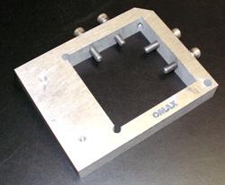
Figure 13 Tooling plate fo adding rectangular holes to an existing part |
Other examples of EDM pallet uses are shown in Figures 12 and Figure 13. Figure 12 shows a small square used much like the larger table-mounted square described earlier. Figure 13 shows a fixture that could be used for machining the square hole in reference to the two existing round holes. The round holes fit on pins, and a clearance hole for the jet is present below the square-hole location. This fixture style also can be implemented for large parts by placing tooling pins in a plate.
If the existing workpiece is large or the quantity to be made is small, it often is impractical to make a holding fixture. If a general-purpose square is inadequate, then the work must be located relative to the machine coordinates by another method. This involves centering the nozzle over a reference location on the part and either noting the coordinates or zeroing the coordinates at that point. If the part is at an unknown angle to the machine axes, a second point must be identified to rotate the part program to match the angle. In this case, locating the nozzle above a point on the work can be accomplished by several commonly used methods.
 |
 |
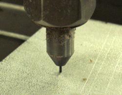
| Figure 14 0.7 mm pencil lead in 0.030-in. mixing tube as a pointer |
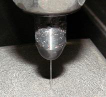
Figure 15 Using a low-pressure water stream as a pointer |
The mixing tube generally is somewhat pointed and can be used as a locating device for holes or circles drawn on the part. Another method is to place a close-fitting wire in the mixing tube bore and then use the wire as a pointer for locating the tube over a part feature. Some users have reported using the replaceable lead from a mechanical pencil for this purpose (see Figure 14).
Another method is to run the jet with tap water pressure with the abrasive off and use the fine water stream as a pointer (see Figure 15).
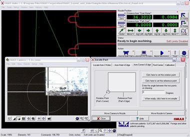 |
| Figure 16 Using a video camera with cross hairs to locate plate corner |
Finally, some manufacturers provide a video camera that mounts at a fixed distance from the jet so that points can be located with cross hairs on the screen of the machine controller (see Figure 16). The strategy to be followed after the points are located depends on the particular control features.


The Fabricator is North America's leading magazine for the metal forming and fabricating industry. The magazine delivers the news, technical articles, and case histories that enable fabricators to do their jobs more efficiently. The Fabricator has served the industry since 1970.
start your free subscription
Easily access valuable industry resources now with full access to the digital edition of The Fabricator.

Easily access valuable industry resources now with full access to the digital edition of The Welder.

Easily access valuable industry resources now with full access to the digital edition of The Tube and Pipe Journal.

Easily access valuable industry resources now with full access to the digital edition of The Fabricator en Español.
In this episode of The Fabricator Podcast, Caleb Chamberlain, co-founder and CEO of OSH Cut, discusses his company’s...


