


Senior Editor
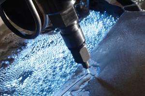
Figure 1Bevels on plate, cuts in barstock and tube, as well as contour cuts on formed sheet can now be performed by the waterjet. Photo courtesy of OMAX Corp.
The abrasive waterjet has attributes unique among cutting technologies. The jet spreads ever so slightly, which creates a tapered cut that becomes especially pronounced on thick material. The slower the jet, the more it diverges to create a conical cut, thin at the top and wide at the bottom. The faster the jet, the more it converges (wide at top, thin at the bottom) as the jet loses penetration near the cut bottom. At the same time, the jet lags, or trails, the faster it cuts, which can reduce accuracy when cutting around corners. Waterjet OEMs have offered tilting head systems that compensate for taper and jet lag. If the head tilts slightly, it moves the jet so that its side contacts the workpiece edge vertically. To make it work, the control must juggle a lot of variables, including speed and part geometry.
After the success of this technology, waterjet machine-makers asked a logical question: What if they could tilt the jet farther, not to eliminate taper, but to cut specified angles? This led to the current state-of-the-art in the waterjet arena: 3-D cutting. Now abrasive waterjets can cut beveled angles into thick plate, cut shapes out of barstock and tubes, and make contoured cuts on a previously formed sheet metal part.
It stems from development work that has transformed the waterjet into a fully controllable, multiaxis cutting system. The technology has existed for years, but much of it has found a home only in specialty applications in which engineers need to cut a solid object made of a material that just couldn't be cut with traditional milling tools.
Today such waterjet technology is finding a new home in sheet metal and plate fabrication, as shops use their machines to cut more than the conventional flat blank.
For many jobs, Airborne Technologies in Camarillo, Calif., receives sheets that are stretch-formed by an outside vendor, and it's Chuck Dollison's job to cut those formed sheets before they go on to further processing (see Figures 1 and 2). It's a job Dollison, supervisor for sheet metal and assembly, used to abhor. He would need to scribe it, cut it with a band saw, then grind it by hand, all of which consumed hours of shop floor time, even for parts with simple contours.
Now contoured sheet metal parts are cut in a few minutes by a waterjet head programmed to move in the Z direction during the cut. The ability to move in Z isn't new technology. Dollison has had his waterjet systems for 10 years. What has been perfected is 3-D programming, a process that has eased most permutations of multiaxis cutting with the abrasive waterjet.
Dollison first lays out the 2-D program, then enters a specialized 3-D editor. There Dollison separates cut lines into segments of varying lengths and assigns a height to each one of them. Segment lengths can be customized depending on the specific geometry of the contour, and each segment can have a different height value.
He does use shortcuts. Not every line segment needs a value if the Z height plateaus over a certain length, for instance. On rare occasions he might spend several hours programming a complex part, but he does this offline, so it doesn't tie up the machine. He must also allow time to develop a fixture, if necessary. If a part contour rises 5 in. from the table surface, the jet will cause the sheet metal to vibrate if the workpiece doesn't have something to secure it. The fixture could be a machined bar supporting the contour from underneath, or something as simple as a support made by a cut-to-length 2-by-4.
As Dollison explained, "The machine may cut through 0.100 in. of sheet metal, and then come upon a vertical flange. Cutting straight down into it means it's cutting through 0.50 in. of material, just for an instant, before going back down to 0.100 in." To accomplish this, the waterjet head must slow momentarily before speeding up to cut the remaining 0.100-in. material.
In thin material, taper and trailback aren't primary concerns. But what if the application involved thick plate? The slowing jet changes its shape, with a less pronounced trailback and a more divergent stream. To maintain a precision vertical cut in thick plate, the control must account for all this and position the cutting head at just the right angle and speed to keep the edge perfectly vertical and burr-free.
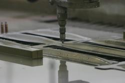
Figure 1This waterjet moves in the Z direction to cut contoured sections of a stretch-formed part. Photo courtesy of Airborne Technologies.
This shape change of the jet with speed is why G and M codes have issues with 3-D waterjet applications, said John Olsen, Ph.D., vice president of technology at Kent, Wash.-based OMAX® Corp. This includes moving in Z as well as tilting the waterjet to cut an angle, such as for chamfering or beveling. For the right applications, abrasive waterjets cut intricate geometries out of thick plate (see Figure 3). Beveled plate that in the past required separate machining for weld preparation now can be cut out of thick plate in one operation.
Before modern controls, this cutting often wasn't practical, taking hours of programming and significant tryout time at the machine, time most contract fabrication shops just don't have. But today is different. Though actual processing performed by the control has gotten ever more complex, front-end programming has gotten simpler.
"When it comes to programming, there are two elements," Olsen said. "The first part is how the user interfaces with the program, and what operators input to get what they want. To the builder of the waterjet, that's the easy part. The hard part for the machine-maker is to determine what moves the waterjet needs to make to get that geometry. That takes a lot more work. And G code doesn't contain enough information to make a good waterjet-cut part."
Consider just a simple cut line in plate that calls for a 10-degree bevel over the first foot and a 40-degree bevel over the next. The operator enters the degree of bevel for each line segment, and perhaps the geometry of the cut lines on the top and bottom of the plate (whether they're parallel or not), and that's about it.
From here the control takes the data points and does some serious computation. Tilting the angle of the waterjet changes the cut thickness (a diagonal line through plate is longer than a vertical one), and with every change in thickness comes a change in speed. And again, as the jet moves slower, the jet shape changes, becoming more divergent and having less trailback. If the cut lines on the top and bottom of the plate are not parallel, the software must compute the continual change in thickness that occurs in the complex bevel, and change the head angle and speed to suit.
Throughout the cut the waterjet controller automatically weighs several factors. First, of course, is the material type. When it comes to material and the abrasive waterjet, "this is where conventional [material cutting] wisdom gets turned upside down," Olsen said, who added that experience shows that "titanium is actually much easier to cut than mild steel, and glass is easier to cut than aluminum." Regardless, he said, abrasive waterjets cut nearly all metallic and nonmetallic materials effectively if parameters are dialed in correctly, and today's controllers do this automatically. Second, the controller considers the material thickness at every point in the cut, and parameters change when angle cutting is thrown into the mix.
One parameter is constant: PSI. "Parameters of the jet pressure are fixed," Olsen explained. "You want to have the most powerful jet on all the time, to get you the most productive jet as possible. The factors that vary are the speed and position of the cutting head, and finding the optimal combination to give you a good part."
Sometimes bevel cutting does require some unconventional approaches, sources said. Consider a compound bevel with a land near the bottom of the plate thickness. This geometry requires two passes: a vertical cut for the land, and an angle cut for the bevel.
It's often fastest to cut vertically first. Bevel cutting first would require the jet to penetrate through a greater thickness and slow the process. If all sides of a part required a compound bevel, the jet would perform the vertical cut, and the plate would float free—not good for an accurate bevel.
In this case, tabbing may be an option. By leaving a small tab at three or four positions on the part, the machine could cut all the needed geometries by performing multiple passes—first the vertical cuts, then the beveled cuts. Depending on the application requirements, part geometry, and plate thickness, removing these tabs after this operation may be more efficient than taking the plate to a secondary beveling process.
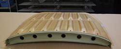
Figure 2This stretch-formed skin was trimmed on a waterjet system, with the cutting head moving in Z. Photo courtesy of OMAX Corp.
Laser tube cutting has been around for years, as has specialized 3-D plasma cutting of tubes. So it makes sense that such technology would enter the abrasive waterjet cutting arena.
Add a specialized accessory to a waterjet with a modern controller and you get a machine that cuts flat plate as well as bars and tubes (see Figure 4 and Figure 5).
In these rotary cutting applications, the waterjet control takes the same factors into account as it does for flat plate: As thickness changes, so does the cutting speed of the waterjet. Consider a 2-in.-diameter round bar. The head will move faster cutting the top portion of the bar and slower when cutting through its central, 2-in.-thick diameter.
In tube applications, a sacrificial bar may be placed in the ID to ensure the jet doesn't mar the wall opposite of the cut. In large-ID applications, tubes can be immersed in water to prevent marring of the inside wall opposite the cut.
The setup of the rotary axis can vary, Olsen explained. "One way is to set the rotary axis at a fixed angle, and the cutting head moves in the XY directions to cut the shape. Then the rotary axis indexes to another angle, and the cutting head cuts another shape. Another configuration involves putting the cutting head directly over the centerline of the rotational axis. In this case, the cutting head moves along this axis while the rotary mechanism rotates the part."
The accessory itself looks a bit like a lathe setup. The spindle nose has an ER collet that holds bars and tubes up to a little more than an inch in diameter; a three- or four-jaw chuck configuration with steady rests can hold larger parts.
Such cutting applications on the waterjet continue to gain a foothold in industry. Several waterjet machine-makers are offering permutations of these capabilities, and many have a common thread: simplified programming. Today's advanced software is making 3-D cutting capability more practical on more fab shop floors (see Figure 6).
As Olsen put it, "People are very inventive, and when they get new technology, they always surprise us with some of the pieces they can make."
Jim Draper, president of Rocky Mountain Waterjet in Greeley, Colo., saves customers money when he can, but he doesn't overpromise. The strategy apparently has worked. The diversified, small waterjet shop of five employees was relatively unscathed by the downturn, and today Draper is considering adding a second shift.
"I can knock on wood and say we have not been through rough times," Draper said. "We have been very fortunate and blessed. The only change we experienced was a slowdown in growth."
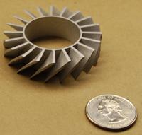
Figure 3This complex part was made with the waterjet head cutting at specified angles. Photo courtesy of OMAX Corp.
He uses his waterjet's tilting capabilities to cut angles when it makes business sense to do so. For one customer in the machinery sector, he cuts a 9-degree bevel in plate that fits into a bowl. The part slides right in with no fuss, and without secondary chamfering operations. He also uses the tilt to cut angles in certain plates that will be machined later. In these cases, the waterjet rough-cuts the edges and saves considerable machining time for his customers.
Draper also uses the waterjet tilt to make chamfered holes in thin material, which has been a huge timesaver. However, he added that he doesn't attempt to cut chamfered holes on thick plate. He explained that if you visualize a jet tilted at an angle, after a certain thickness, the tilted jet of water will cut not only the desired angle, but hit the bottom of the hole as well.
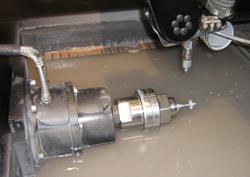
Figure 4A rotary-axis accessory enables the waterjet to cut bar and tube shapes. Here the waterjet cuts a bar into the shape of the Seattle Space Needle. Photo courtesy of OMAX Corp.


The Fabricator is North America's leading magazine for the metal forming and fabricating industry. The magazine delivers the news, technical articles, and case histories that enable fabricators to do their jobs more efficiently. The Fabricator has served the industry since 1970.
start your free subscription
Easily access valuable industry resources now with full access to the digital edition of The Fabricator.

Easily access valuable industry resources now with full access to the digital edition of The Welder.

Easily access valuable industry resources now with full access to the digital edition of The Tube and Pipe Journal.

Easily access valuable industry resources now with full access to the digital edition of The Fabricator en Español.
In this episode of The Fabricator Podcast, Caleb Chamberlain, co-founder and CEO of OSH Cut, discusses his company’s...


