


Product Manager
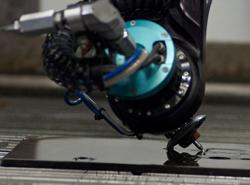
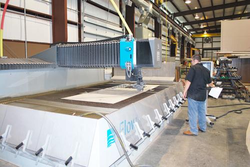
Figure 1: A tilted waterjet head cuts complex bevels and edge contours in plate. The technology has opened up design possibilities on the shop floor.
Abrasive waterjets have evolved into multiaxis cutting systems capable of cutting plate in three dimensions: a compound bevel here, an angled edge feature there, a chamfer over there. The technology has abroadened the designer’s palette and simplified some seriously complex manufacturing challenges (see Figure 1).
Managers at Baytown Ace Machine Co. of Baytown, Texas, had this in mind when they decided to enter the abrasive waterjet arena. In business for 40 years, Baytown is a family-owned job shop specializing in precision machine work and processing equipment repair for petrochemical, industrial, and refining facilities. Quick- turnaround repair makes up a good portion of the job shop’s bread-and-butter work.
“We work to ensure our customers are up and running as soon as possible,” said Josh Kubik, co-owner. “Our customers will bring in a shaft for an impeller hub that needs to be replaced or repaired, or a cylinder to be rolled and formed. If they need it now, they get it now.”
Short lead-time has become a necessity for business survival these days. For this reason, Baytown decided to bring sheet and plate cutting capabilities in-house. The shop also needed some sophisticated bevel-cutting capability. One customer, for instance, requested a blade consisting of a complex radius angle that changed progressively from one edge of the part to the other. Kubik just couldn’t outsource the part; no local job shops had the manufacturing capability. So he opted for a waterjet that could cut complex beveled and 3-D edges into plate and run a variety of materials.
That requirement led him to Flow International’s Mach 4, with its patented Dynamic Waterjet® XD technology. The abrasive waterjet system has a tilting jet head with up to 60 degrees of motion. A laser alignment tool ensures the cutting head is easily aligned to produce accurate cuts.
With the waterjet in-house, the company now has both bevel-cutting capability and flexibility when it comes to materials. “We’re now able to run complex parts in a variety of materials,” Kubik said. “In one day we’ll run 15 different materials ranging from plastics and Teflon® to HASTELLOY® and carbon steel.”
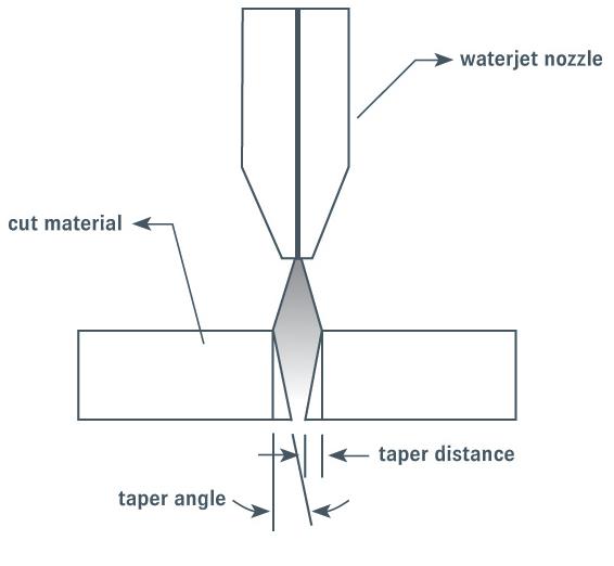
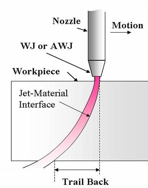
Two naturally occurring elements of abrasive waterjet cutting affect the quality of parts: stream lag and taper (see Figure 2 and Figure 3). Stream lag, or trailback, is the phenomenon in which the exit point of the jet that is cutting the part lags the entrance point. This stream lag causes geometry errors. Taper occurs as the power of the waterjet dissipates while cutting through material. The faster the cut speed, the greater the kerf-taper error, as much as 0.010 inch per side. As with stream lag, the typical way to reduce this taper has been to slow the cutting speed.
When Baytown operators program the waterjet (see Figure 4), mathematical models work behind the scenes to ensure the head tilts to the side to eliminate taper and forward to control the stream lag. In 2-D cutting all this takes place automatically. The operator enters cutting parameters, and the control initiates motion commands to all five axes.
That same technology now is being applied to the 3-D cutting of bevels and other shapes onto plate edges and interior cutouts. Waterjet heads have had the ability to cut complex bevels for years, but it took a qualified technician a long time to program the part properly for the waterjet environment. Today software takes into account the behavior of the waterjet stream, and many of the mathematical calculations are handled under the hood of the controller.
It now takes little time for a machine to process information from a drawing file. The machine controller uses that drawing data to calculate the required motion and speed of the waterjet to produce the part to spec.
Programming in 3-D does require more sophistication in developing a drawing and more care taken in fixturing the part to ensure clamps are properly positioned and the part stays in place during the cut. But because machine programming has become so simplified, the waterjet now can be a practical process alternative for complex bevels.
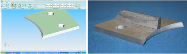
What’s simple to make in CAD hasn’t always been easy to manufacture by traditional methods, but the waterjet has changed the rules somewhat—and some of Baytown’s work illustrates the point. Consider first the precision blade mount shown in Figure 5. The component has a progressively changing radius on its edge, designed to weld to a round impeller hub. The bevel angle actually reverses completely from one side of the part to the other. This is easy to draw in CAD—Baytown uses FlowXpert™, a CAD package that takes the waterjet stream’s characteristics into account. Regardless, the part would have been a bear to manufacture to precision tolerances without developing some complex fixturing and placing the part on a mill.
Without the waterjet, “I would have had to purchase a waterjet-cut part with the holes already cut, and then clamp the piece at an angle to mill a radius on the edge,” Kubik said.
To create this part, the CAD technician created a rectangle, entered the required dimensions, and used the Pull tool to drag the drawing to the proper thickness. Then a cylindrical solid was created with the same OD as the impeller hub and rotated to the desired angle, passing it through the rectangular solid. The Cut tool then was used to delete the cylinder and “excess” material from the drawing. The part took a few minutes to draw in CAD and 8 minutes to cut on the waterjet.
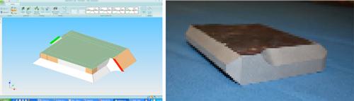
If a thick plate requires complex bevels, like the compound K bevels found in Figure 6, the milling route usually is the only practical option, which can take hours. But managers at Baytown found they could cut this piece on the waterjet.
The part in the figure, a weldment clip that’s used in a variety of industries, is made of carbon steel, but it also can be made from HASTELLOY or stainless steel. In CAD, a technician selected the rectangle icon, entered the dimensions, and then used the point-and-click Pull tool until it was the correct thickness. The K bevel was drawn by selecting the upper edge and then using the Pull tool with the Chamfer option, indicating the size of the chamfer desired. The same was done for the lower edge.
The finished file had three solids sequenced to cut the bottom bevel first, then the flat side, and finally the upper bevel. To create the bevel on the right that blends to a sharp point, the technician split the solid into two pieces by creating a plane and placing it at the point where the chamfered edge stopped. That chamfered edge portion was created by using the Pull tool, again with the Chamfer option selected. The two solids were combined back together, resulting in the chamfer ending in a sharp corner. The sharp corner was then pulled into the proper shape using the same Pull tool, but this time with the Fillet option selected.
Total cutting time for the HASTELLOY version of this 6- by 6- by 1-in. part was 32 minutes.
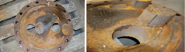
Finally, consider the 1.5-in.-thick carbon steel flange with two angled holes shown in Figure 7. The holes allow pipes to enter at an angle. The customer sent Kubik the flanges with the location of the hole marked, along with a drawing that indicated the desired angle. The CAD technician used the Circle tool to draw the hole cutouts, then the Move tool to rotate them to the desired angle, per the drawing. Altogether, it took 15 minutes to draw.
Kubik estimated that fixturing and cutting those holes at an angle on a horizontal boring mill probably would have taken three hours per flange. But today the waterjet operator fixtures the part, uses a laser edge finder to ensure the cutting head is properly lined up, and starts cutting. He’s finished in 11 minutes, less time than it took to draw the part in CAD.

The Fabricator is North America's leading magazine for the metal forming and fabricating industry. The magazine delivers the news, technical articles, and case histories that enable fabricators to do their jobs more efficiently. The Fabricator has served the industry since 1970.
start your free subscription
Easily access valuable industry resources now with full access to the digital edition of The Fabricator.

Easily access valuable industry resources now with full access to the digital edition of The Welder.

Easily access valuable industry resources now with full access to the digital edition of The Tube and Pipe Journal.

Easily access valuable industry resources now with full access to the digital edition of The Fabricator en Español.
In this episode of The Fabricator Podcast, Caleb Chamberlain, co-founder and CEO of OSH Cut, discusses his company’s...


