Contributing editor
 |
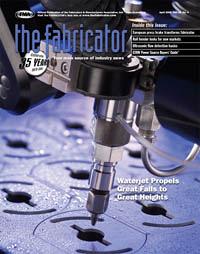
Some fabrication projects come around only once in a blue moon. If a project is commemorative of the bicentennial of the Lewis and Clark expedition, it comes around only once in 200 years. Such was the case with a large and lofty remodeling project at the Great Falls International Airport, Great Falls, Mont., timed and themed to coincide with the historic event.
The airport's new structural features had to reflect the topography and natural features of the region—mountains, streams, plains, and sky, said Project Manager Doug Lorello, CTA Architects Engineers, also of Great Falls. Lorello and his firm had ambitious plans for the project—3-D ceiling components designed to resemble sweeping storm clouds; railing panels with sunset, mountain, and forest scenes cut out in silhouette; and terrazzo floors poured to represent the three regional rivers and their tributaries.
For the fabricators involved, that required thousands of square feet of fabrication—380 ceiling panels; roughly 100 railing sections; large brass lettering identifying the rivers; numerous exterior railings; and signage, as well as some wood and glass fabrication—all within a competitively bid, public-funded budget, and all without ever closing the airport.
Waterjet Extreme Technologies (WET), Great Falls, the fabricator awarded the project, was happy to rise to the challenge. Co-owners John Kramarich and Rip Rippetoe said they viewed the inherent challenges as opportunities to explore the yet uncharted limits of their capabilities. "It was very exciting to get a project like this," Kramarich said. "Plus, we thought maybe we could help put our little town on the map."
It would become a landmark opportunity to enter a whole new level of project caliber. It also would push them to the extremes of their capacities for ingenuity, and fatigue their collective abilities to do great things within a finite budget.
The architects and fabricators worked together to discover ways to streamline costs while achieving the ambitious design goals. "We had a little bit of back and forth between Waterjet and our company, just working out the simplest way to fabricate the components and install them in the field," Lorello said. With steel costing double what it did only a year before, they narrowed in on minimizing material waste to keep the project within budget.
 |
| Figure 1 About 100 sunset, plains, and mountain scenes were cut out of 3/8-in.-thick plate, then fitted into maple, steel, and hammered rod bulkheads. |
The selected cutting process would have to produce very accurate cuts to achieve common-line cutting, perfect fit-up, and smooth cut surfaces that would not require grinding. Also, because a massive amount of metal would be cut out of the railing panels, what remained in the panel had to retain its strength and structural integrity; therefore, the cutting process could not warp or distort the metal. In addition, the architects also wanted all of the fabrication—wood and glass as well as metal—done at one shop.
Kramarich and Rippetoe said they felt that their OMAX® 55100 waterjet cutting machine with a 40-HP pump and a third axis for cutting contours was a good fit for the fabrication project. The close-tolerance cutting required for the intricate cutouts could be achieved on the waterjet, they said. In addition, its cold-cutting properties allowed them to cut the metal without warping it, even at the narrowest sections. "With the waterjet, there is absolutely no heat-affected zone," Kramarich said. "The only thing we had to deal with was the actual stress in the metal panels to keep them flat."
The Sky's the Ceiling. "For the ceiling, we wanted to do something that wasn't just suspended and wasn't just flat," Lorello said. "Initially we looked at premanufactured ceilings, but the cost was out of our budget, so we had to come up with something that would be aesthetically pleasing and still have that cloud look."
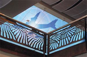
The architects designed 3-D "clouds"—steel mesh affixed to curved frames to be suspended from the ceiling (see introductory photo). "Some of the arcs were designed so that the clouds would have more of a wave pattern out at the ends and some would flatten out toward the center, where we installed a 40- by 90-foot skylight," Lorello said. "So it's kind of a stormy cloud mass moving in toward the skylight."
To fabricate the ceiling panels, WET cut 26 different radius arcs from 12-gauge mild steel in the shop. Then they welded flat strap around the arcs and made a T on each side of them. Next, they cut small brackets, cut holes in them, and welded them to square tubing. Last, they fitted 1/4- by 1/4-in. steel mesh to the frame.
To maximize material usage and save cutting time, the ceiling panel frames were designed to be common-line-cut—that is to say, the right edge of one frame would become the left edge of the next frame. The 4- by 16-ft.-long ceiling components were then brought on-site and painted along with other components by the project's powder coater.
 |
| Figure 2 To maximize material usage, the cutouts from the interior railing panels were used on the exterior railings. |
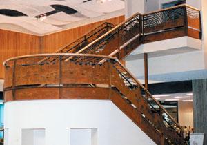
Railing Against the Wind. The sunset, plains, forest, and mountain scenes were cut out of 3/8-in.-thick, 4- by 8-ft. plate, then fitted into C channels and field-welded into maple and steel bulkheads with hammered rod sections (see Figure 1). Cutting out the scenes removed 68 percent to 80 percent of the metal. After the intricate, close-cut profiles were cut, some areas of the remaining blank were as narrow as 3/8 in. It was critical that the remaining skeleton retain its strength and structural integrity. "You're cutting an enormous amount of steel out of a 3/8-inch temper-passed steel plate, leaving big gaps all over. That's the part you're keeping," Kramarich explained.
Another way the architects and fabricators planned to maximize material usage was to salvage the cutouts from the interior railing panels, then attach the cutout pieces to wire mesh railing sections on the exterior of the airport (see Figure 2). "Basically, they're the negative image of what's on the railing panels inside the building," Lorello said. "A double bang for your buck," Kramarich added.
Again, cut quality was critical, not only because they had to achieve common-line cutting on the cutouts, but also because the cuts would be exposed and so had to be smooth and safe to the touch. Furthermore, the cuts—with hairline tolerances within 0.003 to 0.005 in.—had to be as accurate at the panel's parameters as they were in the centers.
The project's plans specified that no grinding be used to smooth out the cut edges. Not only did the architects want to save project costs by eliminating the cost of grinding, they said that if there were any grinding marks, the coating they specified would have revealed them. The coating was a metal oxide primer with an acid sprayed on to make it look like rust, followed by a clear sealer.
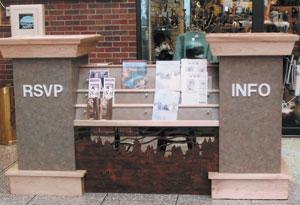 |
| Figure 3 The waterjet's capability to perform multimedia cutting enabled Waterjet Extreme Technologies to fabricate all of the information kiosk's components—wood, glass, and metal. |
Kramarich said that because the waterjet process does not produce slag and was able to cut the plate smoothly, no surface finishing was required. "With the waterjet, we never had to put a grinder on them. We just cut them and sandblasted them to prepare them for the coating, and that was the end of that process."
Both Lorello and Kramarich expressed enthusiasm for the waterjet technology's ability to cut different types of materials and a range of thicknesses.
"The nicest thing about a waterjet machine—it's not the answer to everything, it's also not the fastest piece of equipment on the market—but when it comes to versatility and precision in a multimedia environment, this waterjet will cut anything," Kramarich said. It allows an architect and a fabricator to work with such a large span of materials, so it opens up a whole different market for you in that aspect.
"One minute we can be over there cutting out the wood kiosk panels, and the next second we can have a piece of steel on there, just that fast," Kramarich continued (see Figure 3). "You don't have huge setups to cut these parts. It's on-off, on-off. The jigging is simple. Basically, everything just clamps in."
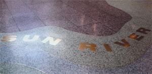 |
| Figure 4 The brass letters inlaid into the terrazzo flooring had to be cut within map line tolerances to achieve palm-in-oar fit-ups. |
Lorello added that being able to have all the steel, brass, wood, and glass fabrication done at one shop allowed his firm to coordinate all the project components better, made the project run more smoothly, and helped to remain within budget.
Streamlining the fabrication of so many components quickly and accurately required good, simple-to-use software, Kramarich and Lorello said.
"The OMAX software we use is not like the old CNC equipment where you had G codes and you had to go in and program each step of the way," Kramarich said. "In essence, we just bring the architect's AutoCAD® drawing into our computer, and all we have to do is go in and tell that computer where to cut those parts out in quick, simple steps, and then go back out and get ready to cut. Lead-in, lead-out, bang, bang, hit the button and it's done."
Kramarich said the software also impacted the project in that they did not have to worry about taper. "They [the manufacturers] take a piece of equipment and design it to take the taper out in the software, which is awesome. It's just unbelievable," Kramarich said. "On the rails and the ceiling, the lettering—taper just wasn't an issue."
The software compensates for taper and jet lag by anticipating the curves, slowing down around curves, and tilting the head slightly, according to Dr. John Olsen, co-founder, OMAX, Kent, Wash. (see Taking out Taper Sidebar).
The nesting software allowed the ceiling arcs to be abutted to reduce material waste. "The waterjet was able to cut extremely close across each arc, so we saved money on the cut—not only on the panel material, but on machine time also," Kramarich said.
 |
| (Left to right): Doug Lorello, John Kramarich, Rip Rippetoe, and Chuck Kjelsrud saw the challenges inherent in a difficult airport redesign project as an opportunity to explore the yet uncharted limits of their capabilities. |
The waterjet technology's capacity for prototyping was a great asset too, Kramarich said. "When you run into a problem—and you always do with a project of this scale—you can prototype it right there and have answers quickly," Kramarich said. "You don't have to sit and wait and go figure out what you're going to do. You can just throw it on the machine and cut it out and say, 'OK, that worked,' or 'OK, that didn't work.'"
Moreover, Lorello said the software and the waterjet's capabilities offered him boundless opportunities for creativity in the design. "Whatever you can think up can pretty much be cut and fabricated, whereas before, with a router or conventional tools, some of these wave patterns and field patterns would have just blown the budget out of the water."
With an appreciative floor-to-ceiling sweep of the airport—from the perfectly crafted railing panels with miles of intricately cut scenes to the gracefully rolling storm clouds to the brilliant, snugly fit brass floor lettering—an observer could easily conclude that the extreme team succeeded in helping put Great Falls on the map—and they didn't need Lewis and Clark to do it.
Waterjet Extreme Technologies, 1620 6th St. N.E., Great Falls, MT 59404, 406-268-0938, getwet@bresnan.net
CTA Architects Engineers, 701 2 St. S., Great Falls, MT 59401, 406-452-3321, dougl@ctagroup.com
OMAX® Corp., 21409 72nd Ave. S., Kent, WA 98032, 253-872-2300, www.omax.com
Photos courtesy of Waterjet Extreme Technologies, Great Falls, Mont.; Alyssa Kramarich, photographer, except where otherwise noted.
The abrasive waterjet is not a rigid tool that simply must be guided along a particular path to make a part. The cutting jet bends back along the path, wobbles from side to side, produces a speed-dependent tapered kerf, and produces a wider kerf when moving slowly. The waterjet's shape at any point along the tool path is a result of multiple independent variables, including the speed and acceleration, all of which affect taper. Compensation for this behavior is essential to economic production of precise parts. Most of these factors are determined during cutting-rate setup.
Moving too quickly results in a wider kerf at the top of the part than the bottom, a poor surface finish, and the possibility that the jet may not cut through the material. Accelerating too hard at a corner causes the jet to kick back and damage the part. As the jet slows, the kerf moves from a taper widest at the top at high speed to a kerf widest at the bottom at extremely low speeds. Moving too slowly, the jet cuts a wider kerf at the bottom of the part than the top and also wastes precious machine time.
Two ingredients are necessary for removing taper—a mechanism for tilting the jet and software that correctly anticipates the taper and drives the tilting head accordingly. The tilting mechanism is attached to the XY table normally used without tilt. It is important that the center of rotation for the tilt be close to the point where the jet enters the top of the workpiece. Otherwise, keeping the jet entry point on the path would require large motions of the XY axes when tilt occurs. The software includes a mathematical model of the cutting process, which anticipates the effects of the jet speed and automatically adjusts the jet motion by tilting the head to make a part with improved accuracy. Combining a jet tilting mechanism with taper-compensating software produces taper-free parts in fractions of the time it takes to make them simply by slowing down the process.
In some cases, the cutting model resides within the controller rather than the CAD/CAM system. These controllers automatically set the speeds based on the material type and thickness and on the part geometry. They handle acceleration at corners to help avoid part damage caused by jet kickback and tilt the head as a function of speed to eliminate slight taper caused by the jet.
Finer abrasives produce a finer surface finish on the cut edge, while cutting at the same rates as coarse abrasives. However, finer abrasives also produce a kerf with more taper than coarse abrasives. A tilting head removes this extra taper and, in fact, all taper so that there is no longer a taper penalty to achieving better edge finish.
Excerpts from Software for abrasive waterjet machines and Improving waterjet cutting precision by eliminating taper by Dr. John H. Olsen, co-founder and vice president of operations, OMAX® Corp., Kent, Wash.

The Fabricator is North America's leading magazine for the metal forming and fabricating industry. The magazine delivers the news, technical articles, and case histories that enable fabricators to do their jobs more efficiently. The Fabricator has served the industry since 1970.
start your free subscription
Easily access valuable industry resources now with full access to the digital edition of The Fabricator.

Easily access valuable industry resources now with full access to the digital edition of The Welder.

Easily access valuable industry resources now with full access to the digital edition of The Tube and Pipe Journal.

Easily access valuable industry resources now with full access to the digital edition of The Fabricator en Español.
In this episode of The Fabricator Podcast, Caleb Chamberlain, co-founder and CEO of OSH Cut, discusses his company’s...