- FMA
- The Fabricator
- FABTECH
- Canadian Metalworking
Categories
- Additive Manufacturing
- Aluminum Welding
- Arc Welding
- Assembly and Joining
- Automation and Robotics
- Bending and Forming
- Consumables
- Cutting and Weld Prep
- Electric Vehicles
- En Español
- Finishing
- Hydroforming
- Laser Cutting
- Laser Welding
- Machining
- Manufacturing Software
- Materials Handling
- Metals/Materials
- Oxyfuel Cutting
- Plasma Cutting
- Power Tools
- Punching and Other Holemaking
- Roll Forming
- Safety
- Sawing
- Shearing
- Shop Management
- Testing and Measuring
- Tube and Pipe Fabrication
- Tube and Pipe Production
- Waterjet Cutting
Industry Directory
Webcasts
Podcasts
FAB 40
Advertise
Subscribe
Account Login
Search
Increasing efficiency of HFI tube and pipe mills
Optical system detects material, alignment problems
- By Pierre Huot
- September 16, 2008
- Article
- Tube and Pipe Production
Manufacturing welded tube and pipe efficiently requires controlling several variables. The material type, gauge, edge condition, tooling setup, and weld heat are just a few of the factors that quality control managers, mill supervisors, and operators must pay attention to in their efforts to achieve output and efficiency targets. In addition to controlling variables to maximize yield and optimize efficiency, they also must meet the quality demands of the market. Mill dynamics, from setup to 0production, ultimately affect each manufacturer's profitability, competitiveness, and reputation.
Of the welding processes used in tube and pipe production, high-frequency induction (HFI) is the fastest, and therefore this market is the most crowded and competitive. Competitive pressures put downward pressure on prices, forcing producers to control costs and reduce scrap wherever possible. Because raw material is 50 percent to 75 percent of the cost of goods sold, a critical step in controlling costs is controlling the many variables in the production process. And monitoring the many variables is the first step in controlling them.
Market Trends
In an industry where the supply and demand curve can swing a firm from profit to loss within a fiscal year, tube and pipe producers face continual pressure from suppliers' steel prices, competitors' capacity, and buyers' quality demands. Energy availability and energy conservation efforts affect profit as well. It is a fiercely competitive industry; producers have little bargaining power, so they need to look to technology to minimize risk.
By its nature, the tube and pipe industry always has been fragmented, unpredictable, and chaotic. The market forces that shape it have forced the survivors to redefine it. The industry has undergone mill maneuvers as firms with heavy coffers acquired or merged with complementary or competing producers. Many have closed plants to relocate their assets to lower-cost countries. With the jostling taking place, experienced mill operators may have been lost in the shuffle, thereby shrinking the experience pool. Many of the remaining players in mature markets and new producers in emerging markets are expanding, increasing competition further among all tube and pipe producers.
Challenges Tube and Pipe Producers Face
In addition to the competitive challenges of the marketplace, tube and pipe producers face many manufacturing challenges. Perhaps the most significant is minimizing variations in strip presentation as it enters the weld section. The phrase "garbage in, garbage out" applies to tube and pipe mill weld boxes as well as it does to its original application, computer software.
A common condition that affects the size and wall thickness after scarfing is nonparallel strip edge presentation as the strip enters the weld area. This usually produces a step, or mismatch, which causes irregular sizing in the sizing area. While it is difficult to root out the main cause of nonparallel strip edges, the two most common causes are:
- Improper setup in the breakdown, forming, or fin section.
- The strip rides higher on one side than the other. This can be caused by strip rolling in the breakdown section or negative tension on the strip. The back pressure from negative tension causes the material to buckle;the energy in the material follows the path of least resistance, which is up the side of a forming roll.
The importance of proper edge alignment cannot be overstated. The growing use of high-strength and ultrahigh-strength steels in thinner gauges further stresses the importance of good edge alignment.
Decrease Setup Time to Increase Production Time. Time is money, and every minute wasted in setup is one less minute for production. Assuming the mill and the tooling have been well-maintained, mill setup is the key to efficiency.
A proper setup achieves the correct V angle, develops sufficient tension, and ultimately produces properly welded tube. Verifying the setup involves threading the mill, producing some tube or pipe, cutting out a length of the product, and subjecting it to a destructive test. If it fails the test, it is necessary to repeat every step, which consumes both time and material.
Setup is not to be taken lightly. A good setup is the first step in reducing scrap, and every little bit helps. While an increase in the scrap rate from 2 percent to 4 percent doesn't sound like much, it is a 100 percent change. In other words, if a mill that generates $10 million in revenue annually with a 2 percent scrap rate experienced a doubling of its scrap rate, its output would have to double to $20 million to maintain the same level of yield.
The Importance of the V. Achieving the optimal V angle and the gap values along the V leading to the apex can help to optimize a mill's efficiency. The V is critical—everything that happens at the V affects weld quality and speed.
Current density is highest at the edges near the apex of the V and at the apex itself. Encouraging high-frequency current flow in the V is a matter of optimizing the V's dimensions and angle.
Optimizing the electrical conditions for the weld is a matter of current flow and edge parallelism.
- A maximum portion of the total high-frequency current should flow in the V. This is influenced by electrical factors such as the design and placement of the welding coil and the use of a current-impeding device mounted inside the tube. It also is influenced by mechanical factors such as the V dimensions and V angle.
- The edges must be parallel in the V for uniform seam heating. Edge parallelism is influenced by mechanical factors such as the shape of the open tube end and the edge condition of the strip. These can be influenced by what goes on in the mill breakdown passes and at the slitter.1
A V angle of 2 to 7 degrees is generally optimal for carbon steel. During production this angle can vary, thereby changing the position of the apex with respect to the weld pressure centerline. The variance can be the result of improper setup, worn forming rolls, or material springback.
All Eyes on the V
The many actions that take place in a mill—numerous forming passes, the welding process, several sizing passes, cutoff, and so on—are too much for an operator to monitor. This is why an extra set of eyes or two would be a big help in monitoring everything that goes on in a mill. It also would be a big help if the extra eyes were calibrated to detect changes smaller than 0.005 in. (130 m).
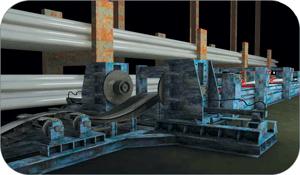
A noncontact optical measurement system fits this description. Designed to assist the operator during setup and production, a properly placed optical device can help prevent faults before production starts and troubleshoot after it starts.
Where can an optical system provide the most value? The two best locations are the most critical ones: at the weld station, near the V, and at the outfeed before scarfing.
Weld Station Infeed. During setup, an optical measurement device in the V-forming area assists in aligning the last fin pass and squeeze roll bottom angle and the forming rolls for proper edge presentation and V angle. During production, it monitors the V angle and gap values in the V by predicting the apex relative to the weld pressure point. It also measures the magnitude of the mismatch between the two strip edges and the distance from the seam roll to the centerline. Finally, the optical device measures edge presentation for parallel strip alignment.
Weld Station Outfeed. During setup, an optical measurement device in the outfeed of the weld box helps in aligning the weld squeeze rolls and in matching the welding parameters to the welding speed.
It does so by measuring the bead's geometry, which indicates cold welds, popouts, or a lack of fusion. During production, it measures the bead geometry for temperature control, measures the bead centerline peak and edge mismatch, and detects weld skips and gaps.
Whether placed at the weld station infeed or outfeed, a control system can compare ongoing measurements with a set of threshold values for lower limit, warning limit, set point, and upper limit. To ensure precise control, the sensors must be capable of data measurements from 0.002 in. to 0.004 in. (50 m to 100 m) and spaced no more than 3/8 in. (10 mm) apart.
Customer Retention, Customer Acquisition, and Profitability
Because the costs of retaining a customer are much less than those associated with losing a customer and acquiring new ones, customer retention is a key strategy for profitability. Depending on the specific application, a pipe or tube failure in the field can result in making site visits to review the installation, drafting reports, and doing research to determine the cause to find a remedy. Another cost is the time necessary to retain the customer or find a new one. Despite all the work that goes into manufacturing welded pipe or tube, the fact is that most of these products are commodities, with low switching costs. In other words, buyers have bargaining power; an unsatisfied client can usually find another supplier quickly and easily.
In short, quality begets market share and builds brands. A single failure can consume a large amount of time and money and cause the producer to lose market share. An inline measurement system can help in preventing such a problem.
Note
1. H. Arthur Link, "Boosting efficiency in solid-state welders," TPJ-The Tube & Pipe Journal®, January/February 1999, p. 38.
About the Author
Pierre Huot
1016 Sutton Drive C5
Burlington, ON Canada Canada
905-331-6660
About the Publication
Related Companies
subscribe now

The Tube and Pipe Journal became the first magazine dedicated to serving the metal tube and pipe industry in 1990. Today, it remains the only North American publication devoted to this industry, and it has become the most trusted source of information for tube and pipe professionals.
start your free subscription- Stay connected from anywhere

Easily access valuable industry resources now with full access to the digital edition of The Fabricator.

Easily access valuable industry resources now with full access to the digital edition of The Welder.

Easily access valuable industry resources now with full access to the digital edition of The Tube and Pipe Journal.
- Podcasting
- Podcast:
- The Fabricator Podcast
- Published:
- 04/16/2024
- Running Time:
- 63:29
In this episode of The Fabricator Podcast, Caleb Chamberlain, co-founder and CEO of OSH Cut, discusses his company’s...
- Trending Articles
Team Industries names director of advanced technology and manufacturing

Orbital tube welding webinar to be held April 23
Chain hoist offers 60-ft. remote control range
Push-feeding saw station cuts nonferrous metals
Corrosion-inhibiting coating can be peeled off after use

- Industry Events
16th Annual Safety Conference
- April 30 - May 1, 2024
- Elgin,
Pipe and Tube Conference
- May 21 - 22, 2024
- Omaha, NE
World-Class Roll Forming Workshop
- June 5 - 6, 2024
- Louisville, KY
Advanced Laser Application Workshop
- June 25 - 27, 2024
- Novi, MI


