


Senior Editor
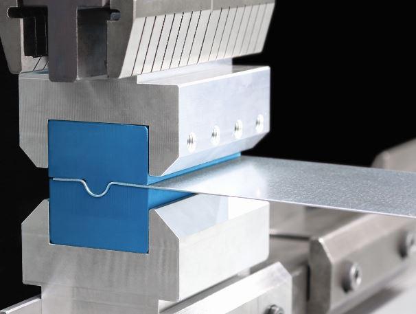
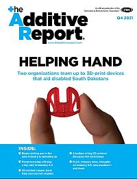
A custom-printed press brake tool creates a rib form in sheet metal. Photo courtesy of Wilson Tool International.
David Olson had an all-too-common conundrum. The director of engineering and technology at Mankato, Minn.-based Jones Metal Inc.scrutinized the prints of an order. One print called for an 8-inch-wide radius in carbon steel, a low-tonnage application. Still, the part geometry requirements eliminated bump bending as an option. In normal circumstances, Olson would have ordered a custom press brake punch and die set. This wouldn’t be a problem for a large order, but this one called for just a few hundred parts. He really couldn’t justify a custom tool.
Or could he? The tool couldn’t be precision-machined out of tool steel, obviously. But did it need to be metal? Could it be a resin or thermoplastic? After all, urethane press brake tools have been used for years for certain surface-critical applications. Why couldn’t a custom brake tool be … printed?
Working with a local Stratasys supplier and service bureau, Jones Metal provided the drawings. The tool produced a very shallow form, which made this a low-tonnage application.
“We knew the forming tonnage wouldn’t be excessive,” Olson said, adding that the material Jones Metal used, a strong thermoplastic called Ultem, had a tensile strength that was well over what the application required.
The tool was printed in a Stratasys FDM printer—at a fraction of the cost of a conventional custom press brake tool set—then tested for use. Ultimately, the tool passed testing and did its job. Another plus: The printed plastic produced a mar-free workpiece. Today the printed tool is sitting in storage, ready to be used when needed.
At this writing the shop has yet to print another tool, but the fabricator is still looking into additive technology in a serious way. And as the industry’s machine and tooling suppliers are finding, Jones Metal is not alone.
The Potential of PlasticWhen a fabrication shop manager sees a 3-D printing machine print a plastic part, layer by layer, myriad applications come to mind. How about a poka-yoke fixture in assembly? A fixture to hold an odd piece for inspection? Perhaps special backgauge fingers on the press brake for the gauging of challenging geometries?
All these applications require forethought, but the printed components involved aren’t put under immense stress. Not so with a press brake tool, of course. And as sources pointed out, developing a tool with additive technology takes more than just picking a material and hitting print.
One big consideration is choosing the printing method. One common method includes fused filament fabrication (FFF), a material extrusion additive process also known under the proprietary names of Fused Deposition Modeling (FDM from Stratasys) and others. In this process, a print head deposits a heated material, like a thermoplastic, layer by layer.
Other methods fall under a category called vat photopolymerization. In these processes, light interacts with a basin of liquid resin, and the exposed areas of resin are converted into a solid part. Processes like stereolithography apparatus (SLA), digital light processing (DLP), and digital light synthesis (DLS) each approach the process in a different way, but they all fall into this category.
At Wilson Tool International in White Bear Lake, Minn., additive manufacturing (AM) is a family thing. The son-in-law of company founder Ken Wilson formed an AM company back in the 1990s.
A die is mounted onto a press brake bed. Photo courtesy of Cincinnati Inc.
“We worked with that additive company for a long time,” said Bryan Rogers, R&D mechanical engineer and additive product specialist at Wilson Tool. “They were our source of 3-D printing for our prototyping. In fact, during most of my career here in R&D, we’ve worked with additive technologies for quite a long time and have slowly brought some of those printing processes in-house.”
For years the company has used 3-D printing technology in its own products. If you see a plastic component on a recently purchased Wilson clamping system, there’s a good chance that component came from a 3-D printer at Wilson’s plant. “We have about 25 part numbers now that are run through additive processes,” Rogers said, “and we have another 80 part numbers that are slated to run through additive processes in the near future.” These parts don’t have high production volumes, and the design of some can change often. Printing simply gets rid of the machining or plastic injection mold tooling costs. “And if we need to change the design, we don’t have to worry about tooling,” Rogers said. “All it takes is an ECR [engineering change request], and we’re good to go.”
With 3-D printers in-house, Wilson’s R&D department has long experimented with jigs, fixtures, and workholding. Many of the company’s kaizen events ended with a request for a printed poka-yoke fixture of some kind. Over the years, engineers ran experiments, printing various tools to see how they would hold up under pressure. During the past few years the R&D effort began in earnest, and all this testing led up to the company’s additive division launch in October 2018.
The division offers two services: printed press brake tools and printed support components. If, say, a fabricator needs a printed brake tool as well as a plastic support component, such as a prototype, fixture, or mold for a sheet metal assembly, it can use Wilson’s 3-D printing services for both of those needs.
Printing a press brake tool can be a lot more complicated than printing a go/no-go gauge. “We tried many different additive technologies and materials,” Rogers said, “to determine what would work best as it pertains to longevity, stress, and part quality, in various configurations. And over time, we narrowed down the choices.”
The company ended up with one resin-based process, DLS, as well an extrusion process, FDM. “We have more technologies coming in-house, but those are the two additive technologies we’ll be using to print tools at the launch,” said Ann Beaupre, Wilson’s product manager for additive.
Rogers added that custom tools will be available for air bending 14-gauge carbon steel and thinner, with equivalent tonnage limits on different material types depending on the tensile strength. The tools will be able to bend lengths 12 in. and less.
Metal and polymer components also are being used together. For instance, the company has printed custom tool sections with intricate indentations designed to form more than a dozen tiny brackets in one stroke, and it mounted those sections onto tool-steel bases.
As Rogers described in another example, “If we have, say, a gooseneck punch that we need to make for a low-marking [surface-sensitive-material] application, we can have the working end of the tool be a polymer material, but the body of the gooseneck would be steel.”
Central to all this has been the company’s lifecycle testing. Rogers and his team have analyzed tool wear up to 1,000 bend cycles, scrutinizing the difference in part quality and tool wear characteristics between the first and last bend.
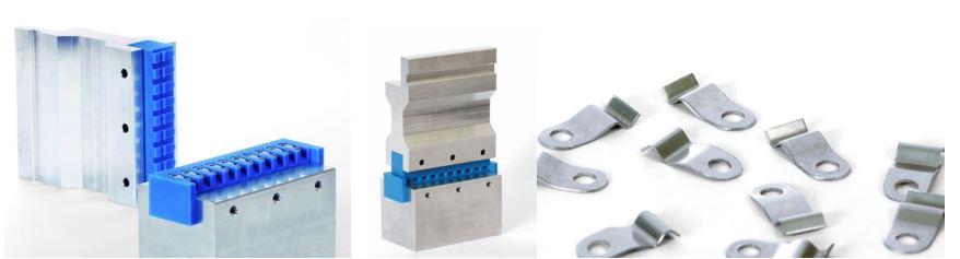
This custom tool set features a 3-D-printed section that can form 10 small clips in a single hit. Photos courtesy of Wilson Tool International.
So how do these printed tools wear? It turns out that they wear the same way as conventional precision-ground tools in an air bending situation. The three points of contact—including the two die shoulder radii and the punch tip—will wear first. “And when bottoming and coining, the wear occurs wherever the material is sliding across [during the bend cycle],” Rogers said.
What the company can build depends on the application tonnage as it relates to a printed tool’s yield point and tensile strength. Identifying them for a specific, printed tool involves testing and finite element analysis.
Analysis is especially important when tackling unusual bend geometries—which, of course, is a big reason to order a custom brake tool in the first place. This includes multibend tools, like offsets and hat channel tools, that make multiple bends during a single stroke. For instance, Wilson has printed tool that makes five bends in a single hit.
“If we form a five-sided box all in one hit, if you use FDM printing, the tool strength will be weaker in one direction,” Rogers said. “So we need to make sure we’re using the right material, so we can compensate for those factors. Or we could switch to a resin [DLS] printing process, which tends to give us better bonding between the layers.”
A 3-D printed tool isn’t for every application, of course. “If we make a tool steel, we obviously can build it to meet the needs of a wide range of applications,” Rogers said. “But when it comes to a printed tool, we have to be a little more selective in what we do.”
A big selling point of AM is the ability to reduce the number of parts going into assemblies, and the same holds true for tooling design. For instance, certain special tool steel dies spring-loaded or bolted components that have to be assembled before the tool is shipped. “When we’ve printed those tools, we’ve been able to eliminate those components,” Rogers said. “But we can print most of those features into a tool. The spring ended up being the only mechanical part we couldn’t print.”
“It’s about having the ability to take a standard tool and look to manufacture it in a different way, and not only to achieve shorter lead times,” said Beaupre, “but also look at ways to create the next generation version of the tool.”
Rogers added that the printed tools aren’t necessarily for operations that need to produce parts to tolerances tighter than +/-0.010 in. —such as applications in the nuclear industry where workpiece material properties and bend processes are controlled to the nth degree. But printed tools can meet the needs of most precision fabricators who need to bend within +/-0.015 in.
Rogers added that the big advantage comes in lead time, and here 3-D printing could solve a pervasive problem among custom fabricators. A request for quote entails several bends that—there’s no getting around it—require a special tool. The shop could get the job, but the tool won’t be available for another 6 to 12 weeks, depending on the supplier. So for the fabricator, that’s probably a no-quote situation. Alternatively, a shop could within days run the job with a printed tool. When and if the job grows into something more, the shop could order a conventionally produced custom tool.
“We’ve already been printing tools for some fabricators, and the jobs that seem to make the most sense involve small runs, such as 100 or 250 pieces,” Rogers said. “The printed tool allows them to start running the job within a few days.”
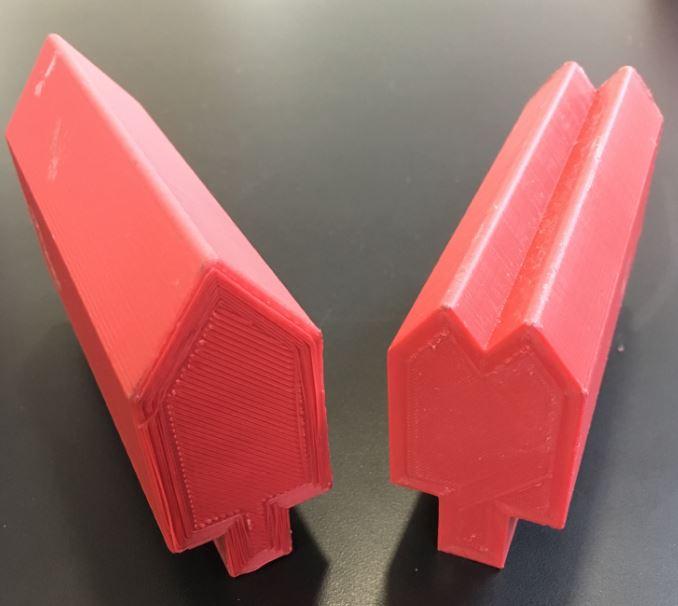
This PLA punch and die were made on a material-extrusion-type 3-D printer. Photo courtesy of Cincinnati Inc.
Cincinnati Incorporated has been an active player in AM for some time, not with metal additive technologies but instead with its extrusion printers such as its BAAM, the Big Area Additive Manufacturing system. Glance at BAAM from afar and you’d swear it’s a laser cutting bed, complete with a gantry and bellows. Get closer, and you’d see the gantry moving a 3-D printing head, depositing thermoplastic to build massive parts, layer by layer.
But even before the BAAM initiative began, engineers within the company had their eye on something much smaller.
“We started on printed [press brake] tooling before we even had the big printer,” said Mark Watson, marketing product specialist at Cincinnati Inc. “We weren’t even in the 3-D printing business yet when I began to test 3-D printed tools. Big questions were, what kind of durability could we get out of a 3-D printed tool, and what kind of accuracy could we get on the part? How would it compare with steel tools? We had 3-D printed tools that matched the geometry of steel tools running side by side in a press brake. And we did statistical analysis of the finished parts.”
The tests entailed not a straight upper punch but a printed gooseneck, a challenging punch geometry when testing for stress under load. Running this printed gooseneck punch and V-die set next to a tool steel punch and die set of identical geometry, Watson ran tests using the same blank of material with the same material thickness and grain direction. Watson knew that the printed gooseneck punch would flex under load, so when it came to bend accuracy, he wasn’t expecting much. But the results told a different story.
“We were really impressed,” Watson said. “We were getting bends to within a third of a degree with the steel tool, and we were within a half a degree or less with the printed tool.”
When the company came out with its own large-format printer, however, the brake tool printing concept was put on hold. Compared with smaller 3-D printers, the BAAM system deposited a relatively thick bead. That bead geometry was critical to the machine’s success at building large parts, but it wasn’t suitable for printing a press brake tool.
Then in 2013 and 2014 Cincinnati began a relationship with a 3-D printing startup based in Boston called New Valence Robotics, or NVBOTS, which among its other products produced a small-format, material-extrusion-based 3-D printer. The startup’s first product shipped in 2016.
“Essentially Cincinnati acted as a value-added reseller, and ultimately this led to us acquiring NVBOTS in November 2017,” said Matt Garbarino, director of marketing communications at Cincinnati.
He added that the startup had been selling many machines into the education market and had started selling a few systems to the commercial market. But with printed brake tools, as well as the potential for other printed manufacturing aids for the fabricator—from poka-yoke fixtures to custom-printed backgauges for the brake—Cincinnati executives saw potential in the metal fabrication arena. Under Cincinnati, NVBOT’s printer came to market as SAAM, the small area additive manufacturing system.
Today the company is testing various tooling designs to failure, pushing them until they break apart and recording the load and stresses. “This is a critical part of all this,” Watson said, “because the safety aspect of running a printed tool is a major concern.”
The company has tested air bending up to 12-ga. carbon steel material “without even stressing the printed tool in a major way,” Watson said, adding that these tests of course used die openings appropriate for the job. In fact, printing a tool would allow a fabricator to dial in the die opening, which could be extremely beneficial for critical jobs with specific radius tolerances called on the print.
Cincinnati’s additive strategy continues to evolve. But at this point the company aims to offer SAAM printers along with programs of tool families that have been tested and certified for effectiveness and safety, so that fabricators can print and use them within specified tonnage limits.
“Now that we see this coming together of the 3-D printing business and sheet metal fabrication, I think the most important aspect of all this is qualifying the tools we’re printing to ensure you know the tonnage limits and you stay safe,” said Chris Haid, general manager of the NVBOTS business unit at Cincinnati. “Just as with traditional metal tooling, printing tooling has an upper limit on what your tonnage can be.”
Haid added that the testing involves several key variables. First is the material, be it a commodity thermoplastic or a proprietary formulation geared specifically for the application requirements. Some applications might benefit from, say, carbon fiber or another composite material. “The beauty of material like carbon fiber is it aids in the stability of the printing process itself,” Haid said. “It reduces thermal distortion and adds a high amount of stiffness to the final part.”
That said, most press brake tools Cincinnati has printed thus far have been out of polyactic acid (PLA) plastic. The material is cost-effective, “and it has enough strength to bend steel,” Watson said. “It’s not the toughest plastic that you could use, and we are looking at other materials. But if we do this right, maybe we don’t have to use higher-strength materials. You can ‘overbuild’ something if you’re not confident of its strength. But if you’re confident in the strength, you can make something safe without overdesigning it.”
“For thinner material, many of the inexpensive thermoplastics can often get the job done,” Haid said. “Material used in each tool can cost around $20 or even less.”
Another key testing variable is the configuration of the 3-D printer itself, including the printer head configuration. For the FFF process, the print chamber itself needs to be warmed and kept at a consistent temperature.
“This avoids any thermal distortion, and the material goes where it needs to go,” Haid said. “And you need to look at the print head and nozzle, which needs to be able to reach the appropriate temperature and print the appropriate bead geometry, so the amount of strength between the printed layers is entirely maximized. You want the strongest part you can get.”
The third aspect of qualification involves the printing program itself, including the path the printing head takes to print the press brake tool layer by layer, as well as the feeds, speeds, layer height, and temperature. A tweak of one variable affects other variables. For instance, if the system prints at a lower temperature, there may be less bonding strength between the layers. At the same time, printing thinner, wider layers can produce better adhesion. And affecting all of the above is the deposition rate, or speed. Tweak the parameters just right, and you can build a stronger tool out of the same material.
“You can use a number of different 3-D printing software [platforms] and change hundreds if not thousands of parameters. You need to dial each of those in so that each is appropriate for the machine and material, to produce a quality part with the required properties.”
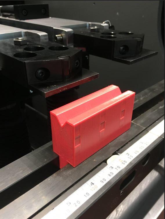
Most of the tools being printed now resemble their tool steel cousins. A printed rib-making tool looks just like the tool-steel version. The printed tool may sit in a metal pocket or channel, but the tool itself mirrors its tool-steel version.
Much talk in AM centers on designing parts for the additive process. This usually means taking a step back and thinking about a component or assembly from an entirely new perspective, one unshackled from the constraints of traditional manufacturing processes.
Additive parts can have interior cooling channels that would be impossible to drill, complicated structures that would be impossible to mill. Biomimicry is everywhere in the additive world because it turns out nature, having benefited from billions of years of evolution, knows how to build things that last.
Could printed press brake tools undergo a similar transformation? Sources couldn’t say, but all agreed that the potential abounds. It all depends on economics, including the part volumes involved and tooling lead times required.
The concept of 3-D printed press brake tools is so new, most foundational groundwork has concentrated on whether additive technology could print an accurate, safe plastic tool that lasts. To do that, engineers have used tooling design concepts that have been around for decades. Further development undoubtedly will build off this groundwork.
Where will this work lead? Who knows? Perhaps the printed press brake tool set of tomorrow will look nothing like the punch and V-die we know today.

In this episode of The Fabricator Podcast, Caleb Chamberlain, co-founder and CEO of OSH Cut, discusses his company’s...
