


Clamping jig aids in mitering, coping, welding at precise locations and angles
Fixturing system makes guesswork obsolete
In a rigidly ordered world, one dominated by predictability and consistency, many tubular projects are straightforward. For any given assembly, the bill of materials usually lists 90-degree angles and consistent lengths. Whether cutting or coping, the prep work and the welding go like clockwork.
However, even in this world, some projects aren’t straightforward. Designs based on curves, whether they are tight-radius bends or gently sweeping arcs, usually leave fabricators scratching their heads. Miter cutting or coping components, and bracing them to an assembly for tacking, can be vexing under the best of circumstances. Sure, most fabrication shops have no small assortment of vises, jigs, clamps, and straps, but cobbling something together leaves a lot be desired. Often a fabricator thinks he’s on Success St., only later to realize that he’s actually stuck at the intersection of Mistake Ave. and Rework Blvd.
Mark, Cut, Clamp, Weld, Distort
A career fabricator and president of Meridian Stainless Inc., Tim Uecker has spent 20 years focusing on two broad categories of custom fabrication work: custom marine hardware and a combination of ornamental and architectural work for commercial, institutional, and residential customers. Although the company works mostly with plate and sheet, it also does quite a bit of tube and pipe work.
“We make a lot of handrails and decorative work for yachts,” Uecker said. “We can’t do any welding on the yacht because the spatter would ruin the deck, so we do the work in the shop.” The challenges start when measuring a yacht’s dimensions, mainly because right angles play a small role in marine applications. From bow to stern and port side to starboard, decks are pitched so they shed water. Making a handrail requires extreme care in measuring dimensions and angles. Most of the intersections between the supports and the handrail are a few degrees from 90 in two axes.
Making the handrail itself usually isn’t too difficult because the rail follows the contours of the deck. However, making the vertical supports and clamping them to the rail for welding bring one challenge after another. Although the company built up a solid body of skill in cutting, coping, and welding to make handrail assemblies, each new project used to generate the same old set of apprehensions: How can I brace these pieces firmly so I can mark lines for coping or miter cutting? Will I get the angle just right, or will I have to grind a bit? Will the heat from the grinder burn off the line I marked before I am finished?
When I get to the welding stage, how much gap will I have to fill? Finally, how much will the welding heat distort the tube?
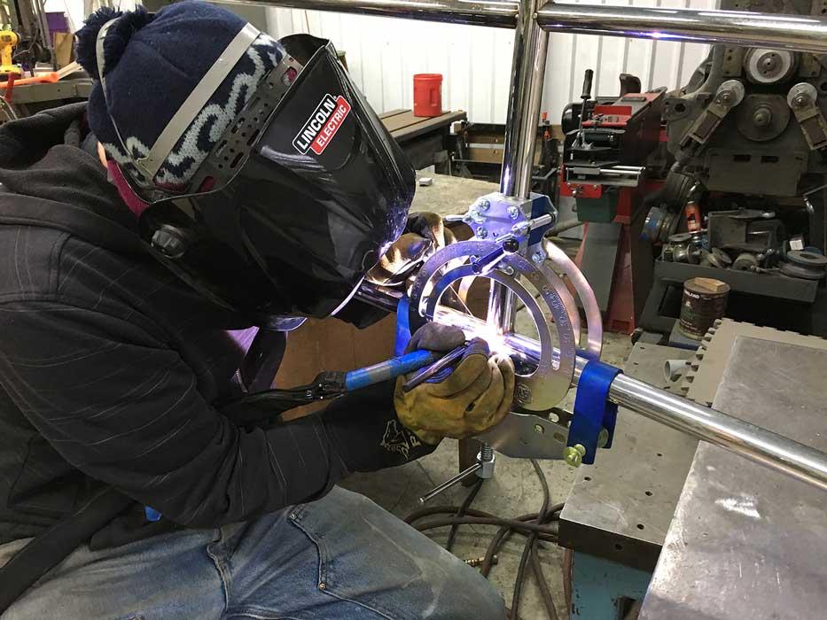
“We tried various combinations of vises and clamps, but that’s not easy because the tubes are round,” Uecker said. “The material is stainless steel, so we can’t use magnets. We use TIG [tungsten inert gas] welding to join the tubes, and that requires two hands, so we don’t have a free hand to hold the tube in place.” Even when a fabricator does find a suitable way to do all of that, the tube isn’t likely to come out straight. The heat from the welding processes is enough to impart a bit of camber to an otherwise straight tube, so fabricators learn to use spacers and clamp the tube tight, bending it slightly in one direction before the weld heat bends it in the other direction, resulting in a straight tube.
“Boat building is steeped in tradition, and one of those traditions is learning on the job,” Uecker said. “These days we have a lot of people with little experience, and few with a lot of experience, but most of those with a lot of experience are retiring. Unless you have a mentor or a reliable system, it can take many years to become proficient at cutting and fitting pipe.”
Like many fabrication shop owners, Uecker was well aware that most of the mentors were close to retirement age, or had retired already, so he searched without success for a fixturing system that would help the less-experienced welders become more proficient.
The Mother of Invention
- The operator affixes the primary clamp to the main tubular member. In the case of a hand railing assembly, this is the horizontal tube.
- The operator attaches the secondary clamp, which resembles a protractor, to the intersecting tube. In the case of a hand rail, this is the vertical support piece. He then connects the two clamps together and orients the support tube to the correct angle and locks it in place. After the angle is set, the user leaves this setting alone.
- The secondary clamp has an index marked in degrees; the user scribes or marks an index line at 0 degrees. The user then advances the tube enough to accommodate cutting or coping to the desired length. The angle and length gauges assist with this step, so no additional marking is required. In other words, the tube stays locked in the clamp until it is welded. The user doesn’t need to make any adjustments to the tube from this point forward. This is the key to how the system works.
- After cutting to length and doing the necessary end prep, the user joins the secondary clamp to the primary clamp. The tube joint now is properly fit and aligned for welding.
Say Bon Voyage to Weld Stress Distortion
The final step is to compensate for weld stress distortion—the main benefit of the system. In the case of a hand rail, the horizontal tube would bend as the weld solidifies and cools. The clamp compensates for bending forces by cambering the horizontal tube in the opposite direction and securing it in place. When the weld is finished, the handrail is straight or it has the intended contour. Although predicting the amount of distortion initially takes a bit of practice, the system makes it easy to dial in the necessary amount of compensation.
“Welders are always shooting for the perfect amount of compensation, whether the workpiece is straight or curved, and this system helps them do that,” Uecker said. The user turns a knob to advance a pressure pad that contacts the tube and keeps right on advancing it, bending the tube just a bit. It takes a couple of practice welds to learn how much to compensate—it depends on factors such as the alloy, the wall thickness, and how much heat and weld metal are applied during the welding process—but after that, it’s repeatable, Uecker said.
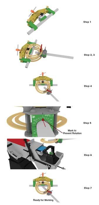
The Angle-Rite® Clamping System consists of two main components: a primary clamp and a secondary clamp. Fixturing and weld prep require seven steps: 1. Affix the main clamp to the main tube or pipe. 2. Affix the secondary clamp to the adjoining tube or pipe. 3. Pin the two clamps together. 4. Set the angle of intersection. 5. If using the angle and length gauge, the tube is ready for cutting or coping. If not, mark an index line on the workpiece and then advance the tube for cutting or coping. 6. Remove the bottom half of the secondary clamp and attach the clamp to the abrasive notcher to make a saddle. 7. Affix the secondary clamp and tube to the primary clamp and tube. The tube assembly now is ready for welding.
An animation that shows the sequence can be viewed at www.anglerite.com.
Meridian Stainless Inc., www.meridianstainless.com
About the Author

About the Publication
subscribe now

The Tube and Pipe Journal became the first magazine dedicated to serving the metal tube and pipe industry in 1990. Today, it remains the only North American publication devoted to this industry, and it has become the most trusted source of information for tube and pipe professionals.
start your free subscription- Stay connected from anywhere

Easily access valuable industry resources now with full access to the digital edition of The Fabricator.

Easily access valuable industry resources now with full access to the digital edition of The Welder.

Easily access valuable industry resources now with full access to the digital edition of The Tube and Pipe Journal.

Easily access valuable industry resources now with full access to the digital edition of The Fabricator en Español.
- Podcasting

In this episode of The Fabricator Podcast, Caleb Chamberlain, co-founder and CEO of OSH Cut, discusses his company’s...
- Trending Articles
1
Team Industries names director of advanced technology and manufacturing

2
Orbital tube welding webinar to be held April 23

3
Chain hoist offers 60-ft. remote control range

4
Push-feeding saw station cuts nonferrous metals

5
Corrosion-inhibiting coating can be peeled off after use
