


Analyzing the k-factor in sheet metal bending
A deep dive into the k-factor, what it is, and why it matters
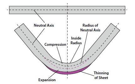
The thinning sheet forces the neutral axis to shift inward toward the inside bend radius. Describing that shift is what the k-factor is all about.
This is the first part of a two-part series. For the second part, click here.
It started innocently enough. A reader wrote me asking me about the k-factor and calculating bend allowances. I explained how the k-factor was used and referred him back to the usual k-factor charts. The reader thanked me for the response, but then said he wanted to know more. Where do these k-factor values come from, and how do you calculate them without a chart?
One thing led to another, and I eventually found that to give a complete answer, my journey would take me not only to k-factor calculations, but the y-factor, minimum radii, kinetic friction, and grain directions—all key ingredients that make the sweet, subtle, complicated gumbo that is the science of bending. That said, let’s get cooking.
Why the k-Factor Matters
Of all the mathematical constants used in precision sheet metal fabrication, the k-factor stands out as one of the most important. It’s the base value needed to calculate bend allowances and ultimately the bend deduction. It’s a mathematical multiplier that allows you to locate the repositioned neutral axis of the bend after forming.
Once developed, the value of the k-factor will enable you to predict the total amount of elongation that will occur within a given bend. The k-factor allows you to calculate the bend allowance, the outside setback, the bend deduction, and the flat layout of the precision part you’re forming.
Defining the Neutral Axis
To understand the k-factor, you need a firm grasp of a few basic terms, the first being the neutral axis. The neutral axis is a theoretical area lying at 50 percent of the material thickness while unstressed and flat. The neutral axis is a shifty guy; that is, it shifts toward the inside of the bend. The theoretical line of the neutral axis will remain the same length both before and after the bend is complete.
During bending, while the area between the neutral axis and the inside surface comes under compressive forces, the area between the neutral axis and the outside surface is stressed by tensile forces. The neutral axis is the zone or plane that separates the tension from the compression. The neutral axis position depends on the bend angle, inside bend radius, and method of forming.
The neutral axis’s behavior is the main reason the flat part needs to be smaller than the total of the formed piece’s outside dimensions. Look closely a Figure 1. Notice how the sheet has thinned at the bend. This 10- to 15-percent thinning during the bend forces the neutral axis to move inward, toward the inside surface of the material.
Defining the k-Factor
The k-factor has more than one definition, as we’ll discuss in future columns in this series. That said, you can find the classic definition for k-factor from various sources. The one that follows comes from the Department of Mechanical and Production Engineering, Ahsanullah University of Science and Technology in Bangladesh.
The k-factor is a constant determined by dividing the location of the shifted neutral axis by the material thickness of the sheet. The area within the sheet defined as the neutral axis does not get compressed on the inside of the neutral axis or expanded on the outside. The neutral axis does not suffer any change [of] length during a bending operation.
“However, the neutral axis does move toward the inside surface by a percentage, that percentage being the k-factor. This relocating or shifting of the neutral axis—from 50 percent of the material thickness to a new location equal to or less than 50 percent of the material thickness—is the reason why the part elongates during forming. The linear distance around the arc of the bend at the neutral axis is where the bend allowance measurement is taken.”
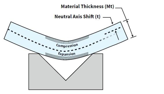
Say you have a 1-millimeter (mm) material thickness. In a flat state the material has a neutral axis located at 50 percent of the thickness, at 0.5 mm. Bend the material, and the neutral axis shifts to 0.446 mm, as measured from the inside surface of the bend. We define this neutral axis shift as t, as shown in Figure 2. We calculate k-factor by dividing t by the material thickness (Mt): k-factor = t/Mt,
The k-factor is nothing more than a multiplier that can give you an accurate value for the relocated neutral axis. And if you know the bend allowance, you can extract the k-factor from it. Once you know the k-factor, you can use it to predict the bend allowance for various angles.
The k-factor is fundamental to designing precise sheet metal products. It allows you to anticipate the bend deduction for a large variety of angles without having to rely on a chart. While modern bend deduction charts now are reasonably accurate, historically bend calculation charts, both for bend allowances and bend deductions, were notorious for their inaccuracies. They were usually only valid for the manufacturing environments in which they were created. And many of these charts are still floating around.
The k-factor isn’t perfect. For instance, it does not consider any of the stresses and strains that develop within the bent material. And deriving the k-factor also depends on the tooling you use, the type of material, the tensile and yield strength, the forming method (air forming, bottoming, or coining), and other variables.
The chart in Figure 3 shows the range of k-factors you can have, from 0.50 all the way down to 0.33. And the k-factor can be even smaller. In most applications, the k-factor is given as an average value of 0.4468.
You’ll never see a k-factor larger than 0.50 in a practical application, and there’s a good reason for this. The compressive stress of the bend cannot exceed the outside tension. When the sheet is flat without any applied stress, the neutral axis is in the middle of the sheet. But add a little stress and force the metal to bend and watch what happens. The granular bonds are stretched, pulled, and sometimes break, forcing the grains apart as they come under tensional stresses.
This is Poisson’s Ratio in action; when material is stretched in one direction, it gets shorter in the other direction. Poisson’s Ratio explains why the outer area of the cross section of a bend is greater than the inner region. As space expands on the outside of the bend, it shrinks on the inside. Look at the edge closely in Figure 4, and you can see material expanding on the outside of the bend, compressing on the inside, forcing the inside edge of the bend to “convex.”
The k-Factor and Minimum Bend Radius
A common problem in both the sheet metal and plate industries involves parts designed with an inside bend radius much tighter than necessary. It can wreak havoc in the press brake department and cause cracking on the outside surface of the bend.
A bend made too sharp develops plastic deformity from the excessive stress caused by the bending. The problem will manifest itself as fracturing on the outside surface, altering the bend allowance. The smaller the inside bend radius, the more the neutral axis will shift toward the inside surface of the bend.
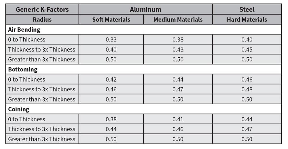
Figure 3
This generic k-factor chart, based on information from Machinery’s Handbook, gives you average k-factor values for a variety of applications. The term “thickness” refers to the material thickness. A k-factor average of 0.4468 is used for most bending applications.
A big driver behind this is the use of the term “minimum bend radius” on many drawings, and how that term is interpreted. Many see “minimum bend radius” and reach for the sharpest punch they have, the one with the smallest punch tip radius.
The minimum bend radius is a function of the material, not the radius on the punch. In an air form, it is the smallest inside bend radius you can achieve short of bottoming or coining the material.
If you air form with a punch radius less than the minimum floated radius, you will crease the inside center of the bend, creating a sharp bend. As variations in the material manifest, part-to-part material changes amplify any normal in angle deviation, ultimately causing dimensional errors in the workpiece. (For more on sharp bends, type “How an air bend turns sharp” in the search bar at www.thefab ricator.com.)
The minimum bend radius takes on two distinct forms, both of which affect the k-factor in the same manner. The first form of a minimum radius is at the borderline between “sharp” and “minimum” radius in an air form. This is where the pressure to form is more significant than the pressure to pierce, ultimately creating a crease in the center of the bend and amplifying any material variations. When the punch nose penetrates the material, it further compresses the inner area of the bend, resulting in changes to the k-factor.
The second form of minimum inside bend radius is created by the ratio of the bend radius to the material thickness. As the ratio of inside radius and the material thickness decreases, the tensile strain on the outer surface of the material increases. When the ratio
This is made worse when the bend line is parallel to the grain or rolling direction of the sheet metal. If the bend in a given piece of metal is bent with a sharp punch-nose radius relative to the material thickness, the grains in the material expand much farther than they would if the radius were equal to the material thickness. This again is Poisson’s Ratio at work. When this happens, the neutral axis has no choice but to move closer to the inside surface as the outside of the material thickness expands farther.
This second form of minimum bend radius is therefore defined as the “minimum bend radius for a material thickness.” This is usually expressed in terms of multiples of the material thickness—2Mt, 3Mt, 4Mt, etc. Material suppliers offer minimum bend radius charts that define minimum radii for various alloys and tempers of those alloys.
Where do these numbers in the minimum radius charts come from? They involve other ingredients that spice up our k-factor gumbo, including ductility. A tensile test measures ductility, or a metal’s ability to undergo plastic deformation. One measure of ductility is the reduction of area, also known as the tensile reduction of area. If you know a material’s tensile reduction value, you can perform a rough estimate of the minimum bend radius, depending on your material thickness.
For the minimum bend radius in 0.25-in.-thick material or greater, you can use the following formula: [(50/Tensile reduction of area percentage) – 1] × Mt. For the minimum bend radius for material less than 0. 25 in. thick, you can use this formula: [(50/Tensile reduction of area percentage) – 1] × Mt} × 0.1
In these equations, you use the percentage as a whole number, not a decimal. So, if your 0.5-in.-thick material has a 10-percent reduction percentage, instead of using 0.10 in the equation, you’d use 10, as follows:
[(50/10) – 1] × 0.5 = 2
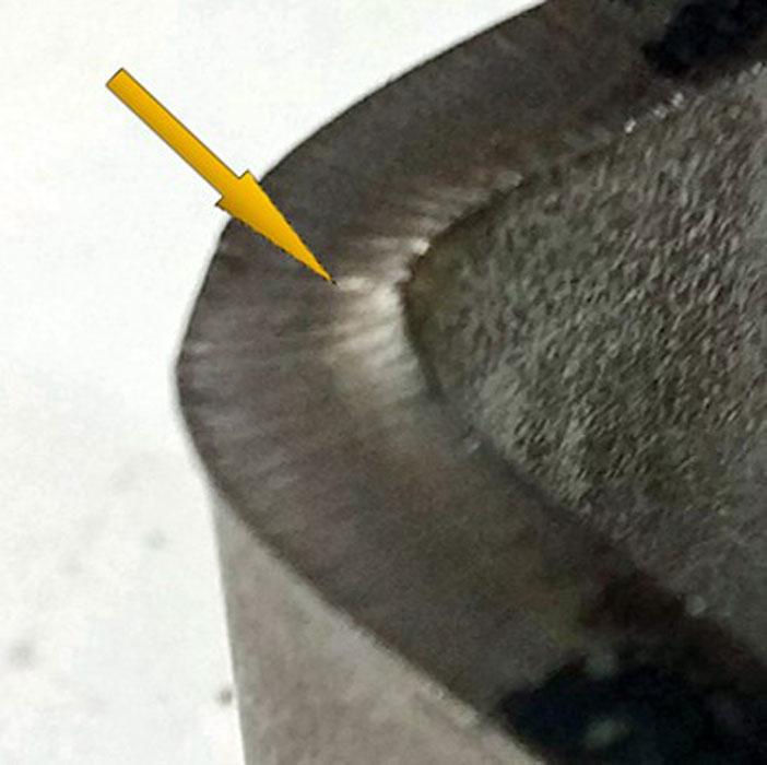
Figure 4
Compression on the inside of the bend forces the inside edge to “convex.”
In this case, the minimum inside bend radius is two times the material thickness. Note that this is just a rule of thumb that gives you a ballpark figure. Finding the correct minimum bend radius for steel or aluminum plate requires a little research and should include data from your material supplier and another critical ingredient in your k-factor gumbo: whether you are bending with or against the grain.
Grain Direction and k-Factor Bend Allowance
The grain direction, created in the direction the sheet is rolled at the mill, runs the length of the full sheet. You can see it on a new piece of sheet metal by noticing the direction of visible lines running through it. When the sheet is made, its particles become elongated in the direction of rolling.
Grain direction is not a surface finish, which is made by sanding or other mechanical procedures. Nevertheless, finish surface scratches do make the material more susceptible to cracking, especially when the finish grain is parallel to the natural grain.
Because the grains are directional, they cause variations of the angle and, potentially, the inside radius. This dependence on orientation is what we call anisotropy, and it plays an important role if you want to make precise parts.
When the metal is bent parallel (with) the grain, it affects the angle and radius, making it anisotropic. Incorporating the metals anisotropy qualities are an essential part of making accurate predictions for k-factor and bend allowances.
Bending with the grain forces the neutral axis inward, changing the k-factor once again. And the closer the neutral axis gets to the inside surface of the bend, the more likely cracking is to occur on the outside of the radius.
While it requires less force to bend with than across the grain, a bend made with the grain is weaker. The particles pull apart easier, which can lead to cracking on the outside radius. This can be amplified by bending sharp. That said, if you’re bending with the grain, it’s safe to say that you’ll need a larger inside bend radius.
Material Thickness and Hardness
We have two more ingredients: material thickness and hardness. As the material thickness increases relative to its inside radius, the k-factor value gets smaller, again pushing the neutral axis closer to the inside surface. (Note that this assumes you’re using a die opening appropriate for the material thickness. The die width has its own effect on the k-factor, which we’ll cover next month.)
The k-factor also gets smaller with hardness. Harder materials require more stretching just to come to an angle. That means a greater area of tension on the outer side of the neutral axis and less space on the inner side. The harder the material, the larger the necessary inside radius, sometimes reaching into multiples of the material thickness. It’s Poisson’s Ratio at work again.
More k-Factor Ingredients to Come
I’ve covered only some of the ingredients that go into the k-factor gumbo. Next month I’ll cover more ingredients, including the die width, the coefficient of friction, y-factors, and, not least, the bending method: air bending, bottoming, or coining. I’ll also discuss another kind of K-factor (this one with the “K” capitalized).
Then I’ll walk you through a bend calculation from scratch, compete with a manual calculation of the k-factor. All this will show that, yes, using the commonly accepted k-factor value of 0.4468 makes a fine gumbo. It gets you darn close to perfect for everyday use. But by using a k-factor calculated specifically for the application, you can get even closer—and the gumbo will taste even better.
About the Author

About the Publication

subscribe now

The Fabricator is North America's leading magazine for the metal forming and fabricating industry. The magazine delivers the news, technical articles, and case histories that enable fabricators to do their jobs more efficiently. The Fabricator has served the industry since 1970.
start your free subscription- Stay connected from anywhere

Easily access valuable industry resources now with full access to the digital edition of The Fabricator.

Easily access valuable industry resources now with full access to the digital edition of The Welder.

Easily access valuable industry resources now with full access to the digital edition of The Tube and Pipe Journal.

Easily access valuable industry resources now with full access to the digital edition of The Fabricator en Español.
- Podcasting

In this episode of The Fabricator Podcast, Caleb Chamberlain, co-founder and CEO of OSH Cut, discusses his company’s...
- Trending Articles
1
AI, machine learning, and the future of metal fabrication

2
Employee ownership: The best way to ensure engagement

3
Steel industry reacts to Nucor’s new weekly published HRC price

4
Dynamic Metal blossoms with each passing year

5
Metal fabrication management: A guide for new supervisors
