


How to check the performance of your press brake and tooling
Focusing on the wrong metric can be a quixotic pursuit
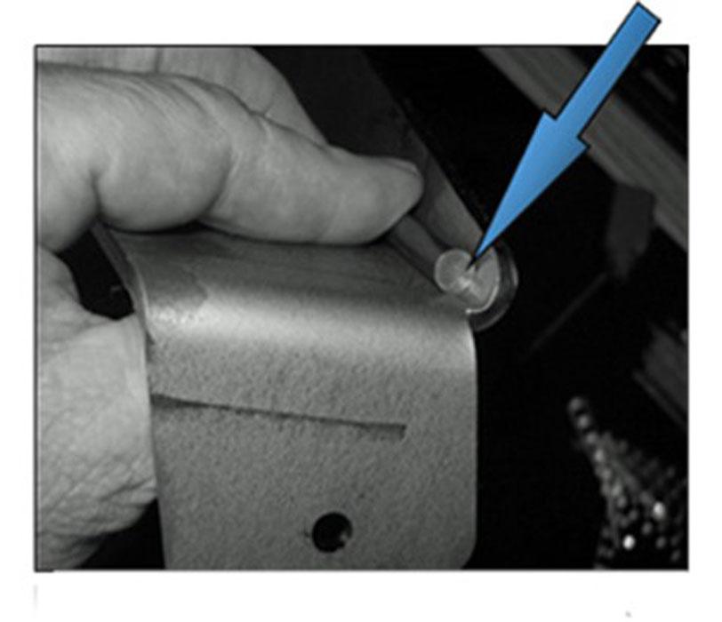
Figure 1
A pin gauge is used to measure a bend radius.
Question: We are creating a quality program where we will run coupon parts to verify certain machines, including our press brakes, are in good working condition. The idea is to identify and resolve potential issues before we get a string of them on production parts. We will be running various coupon materials and thicknesses, and one of the measurements from the press brake operation will be the inside radius of the form. We now are kicking around a few ideas on how to accurately and consistently measure this, but we are looking for help. What type of measuring instrument would you use if you were to measure the inside radius of a formed flange?
Answer: If you’re looking for a way to ensure that your press brake is in top form, the inside bend radius wouldn’t be on the list, and here’s why. If you are air forming, the radius is a function of the die width; that is, the inside bend radius forms as a certain percentage of the die opening. We call this the 20 percent rule, though our baseline material is 60-KSI mild steel, which forms at about 16 percent of the die opening.
If you are bottoming or coining, the inside radius is a function of pressure and the punch nose. The radius is more or less “stamped” into the part. Bottoming and coining also are very operator-dependent, and it really becomes a judgment call as to how much pressure or depth of penetration a particular part requires to make a specific bend.
For more on the 20 percent rule and how it all fits together, I recommend you read “A grand unifying theory of bending,” a four-part series archived at thefabricator.com. You can find the articles by typing the title in the search bar. You also can find the material at theArtofPressBrake.com, along with many other columns and articles on the topic.
Regardless of how it is created, the inside bend radius has far too many variables to be used as a unit of measure for ensuring a press brake is functioning properly over time. Tilting at windmills, you’ll be quixotically attacking imaginary enemies, as myriad variables—many of which have nothing to do with the press brake’s health—cause the inside bend radius to change.
Dissecting the Radius Metric
The inside bend radius is, however, an excellent metric for studying the health of your tooling. This measurement relies on the consistency of your tool selection and use.
Still, material variations affect the inside bend radius you achieve. So if you do assess your tooling by measuring the inside bend radius, you need enough coupons of the original reference material for testing over time. These reference coupons will provide what any good quality program needs: precise data points.
Air forming floats the radius as a percentage of the die opening. This makes a standard radius gauge basically useless for any real accuracy. Out of the box, these gauges have standard sizes such as 1/8 inch, 5/16 in., 3 millimeters, or 4 mm. Your parts can have any number of bend radii between these set values.
One radius gauge option, though, would work in production. With a laser you could cut individual radius gauges, scaled up or down as needed. These gauges would then travel with the job jacket, or be placed in the press brake tool area or in quality control.
Your second option is to use a pin from a pin gauge set. Shop-grade pins would work fine for this. To use them, pick the radius that you need and drop a pin gauge into the center of the bend to determine the size of the radius (see Figure 1). Using these is still somewhat subjective, just as the radius gauge set is, but a good pin gauge set should give you a complete selection of diameters to choose from, in metric or imperial units.
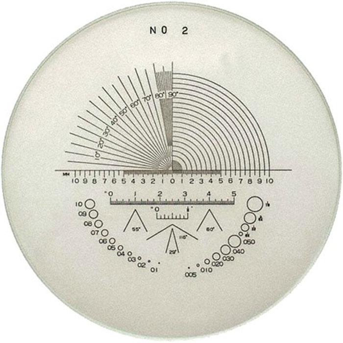
Figure 2
To measure your inside bend radius, you can use a portable optical comparator that has a reticle with radius markings.
The most accurate option is to use a hand-held optical comparator. You’ll need the comparator and a reticle (which gives you lines in the sighting device) marked for radius measurement (see Figure 2).
The final way to check the inside radius is mathematical. Start by measuring the coupon both before and after bending. That difference is the bend deduction. Compare that value either to the original numbers for the required inside radius or use that value to “back figure” the actual inside radius of the part. For more on this and the basic bend formulas, see “The basics of applying bend functions,” archived at thefabricator.com.
Metrics for Checking the Press Brake
To check the press brake itself for repeatability and accuracy, I recommend focusing on four areas: ram repeatability, the reproducibility of the backgauge location, possible damage to the ram and bed (ram upset), and the availability of consistent tonnage.The first three all require a mag-base and a dial indicator. Make sure the top of the bed and the bottom of the ram are clean and free of burrs or visible damage. Preparing it may require you to “dress off” both surfaces with a very fine sharpening stone. Remember, you’re only cleaning and removing burrs, not modifying the bed and ram.
With the ram in its closed position, take your mag-base and dial indicator and slowly move from end to end. You should see the dial indicator needle move slightly up and down (or back and forth) as you move over minor surface imperfections. You should not see the indicator’s needle move one way as you move toward the center and then move the other way as you reach the other end. If it does, it is a sure indication of ram upset. Ram upset should be professionally repaired by someone with the right equipment.
You could see the needle gradually decrease or increase its reading over the entire length of the bed; this tells you that the ram is out of parallel (the Ty axis). The operator can correct this at the press brake controller by using the ram tilt adjustment. If fine-tuning doesn’t correct the problem, you may need to call on your maintenance department.
Next, with the ram at the bottom of the stroke, set up the dial indicator again to take a reading. Cycle the ram several times, and then watch and see if the ram returns to the same reading every time. Modern ram repeatability is measured in microns, so the reading should be the same.
After this, check the Tx axis. The Tx axis involves the relationship between the bend line and the backgauge. Start by measuring the body of the die you intend to use, and then load two sets of that tooling into the press brake, one at each end of the bed and under a light load. Now, send the backgauge to its origin or reference position. If you are unsure of what the location dimension is, check the press brake’s service manual for that information. On many machines it’s at 4 in. Add half of the die body width (not the die opening) to that number, and measure from the front of the die to the front of the backgauge. It should precisely match the calculated value of the reference plus half of the die body width. Move the backgauge and re-reference the gauge several times to ensure it consistently finds its home position.
Take a second dial indicator and set them both to take a reading from the stops themselves; the farther apart the two dial indicators are, the better. Then send the backgauge out and then back to position again to check the repeatability.
The last check is the repeatability of the press brake’s hydraulics or drive system. Without a unique tool for measuring pressure, you will need to rely on the press brake’s controller. The data should be available, though unfortunately it’s often buried in the technical data collected by the controller. The data may also be password-protected. Nonetheless, with a little research, patience, and practice, you’ll be able to access the information about the health of the hydraulic system anytime you need to know.
Press Brake and Tooling: Good to Check Both
Regardless of the way it is developed in the workpiece, the inside bend radius is the wrong metric for monitoring your press brake’s health. But again, measuring the inside bend radius is a good practice to follow to check your tooling.
Monitoring your press brake’s health definitely has merit, as does checking the health of your tooling. In fact, it’s best practice to check both. After all, a press brake in pristine condition will still produce bad parts if it has bad tooling.
Steve Benson is a member and former chair of the Precision Sheet Metal Technology Council of the Fabricators & Manufacturers Association International®. He is the president of ASMA LLC, steve@theartofpressbrake.com. Benson also conducts FMA’s Precision Press Brake Certificate Program, which is held at locations across the country. For more information, visit www.fmanet.org/training, or call 888-394-4362. The author’s latest book, Bending Basics, is now available at the FMA bookstore, www.fmanet.org/store.
About the Author

About the Publication
subscribe now

The Fabricator is North America's leading magazine for the metal forming and fabricating industry. The magazine delivers the news, technical articles, and case histories that enable fabricators to do their jobs more efficiently. The Fabricator has served the industry since 1970.
start your free subscription- Stay connected from anywhere

Easily access valuable industry resources now with full access to the digital edition of The Fabricator.

Easily access valuable industry resources now with full access to the digital edition of The Welder.

Easily access valuable industry resources now with full access to the digital edition of The Tube and Pipe Journal.

Easily access valuable industry resources now with full access to the digital edition of The Fabricator en Español.
- Podcasting

In this episode of The Fabricator Podcast, Caleb Chamberlain, co-founder and CEO of OSH Cut, discusses his company’s...
- Trending Articles
1
How to set a press brake backgauge manually

2
Capturing, recording equipment inspection data for FMEA

3
Tips for creating sheet metal tubes with perforations

4
Are two heads better than one in fiber laser cutting?

5
Hypertherm Associates implements Rapyuta Robotics AMRs in warehouse
