


How to set up an old press brake
Maintained and operated properly, old brakes still can produce good parts
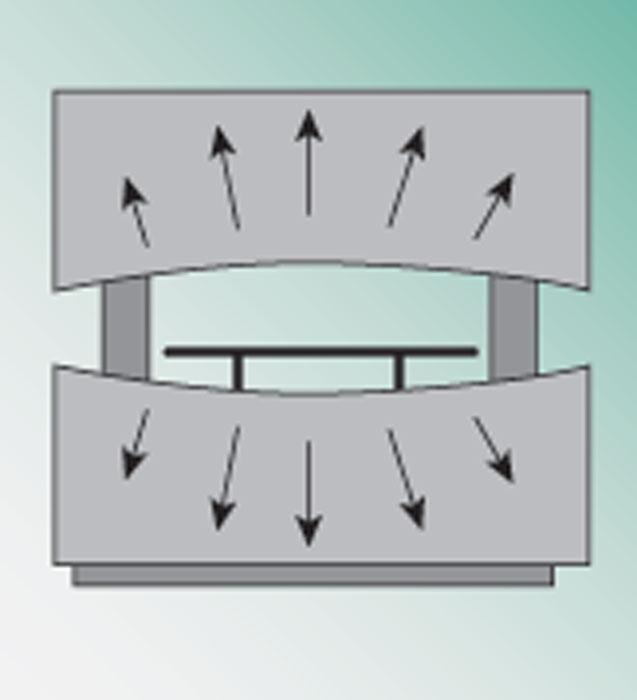
Figure 1
If your dial indicator reading gets larger and then smaller as it’s moved along the bed, the brake is suffering from ram upset.
Question: I have been reading your columns for years and I have found them to be a wealth of information. However, in all those years there is one topic you have yet to cover: the basic press brake. I recently took a position in a small job shop, where we work with an old mechanical press brake with tooling that’s obviously from a different time, although both the machine and tooling have been well-maintained.
I am sure many of us are still using these older mechanical press brakes, or press brakes that are just a little more basic than the state-of-the-art systems you usually discuss. How about throwing us a bone and explaining how to set up and run one of these simpler machines?
Answer: Sir, that would be my pleasure. Let’s talk about how to start. First, find the press brake manual if it’s still available. If you can’t find it, look around the internet and try to locate a copy. Once in hand, look it and your press brake over. Make sure everything is properly adjusted. Are the gibs that guide the ram loose or worn out? Check the brake and clutch assembly, and make sure they are working as designed. If the ram has to make three revolutions before coming to a stop, something’s wrong.
Check to see if the press brake mechanics are in good working order. If they’re not, you may have a real safety problem. If you’re comfortable that they are in good shape, then start prepping the working area of the press, this being the bed and the ram.
Remove the bolster from the press, take a very fine file, and dress off the bed of the press and bolster. Remember, you’re only knocking off burrs and high spots created from years of use; you’re not trying to modify the press brake.
On the bolster, be sure to dress out the channel where the die’s mounting tang is inserted. Also, if you find any locking screws or bolts in the bed, remove them. Keep only four, two at both ends of the machine bed.
Take all of the clamps from the ram. Clean the surfaces of the clamps and dress the bottom of the ram. Before reassembling the clamps, find a dial indicator and a mag base. Assemble the indicator and base to take a reading between the bed and ram. Now, slide the base and indicator along the length of the bed while watching the dial. You should see the dial move slightly, reacting to surface imperfections. You shouldn’t see the dial indicator reading get larger as you approach the center of the bed and then get smaller
If you see the reading climb at the center of the ram, the brake is suffering from ram upset, which means that the ram has been bent (see Figure 1). Even if you shim at the center, the press brake is never going to work correctly until it is machined back to flat. Both the bed and ram will need to be repaired.
If the dial reading gets either larger or smaller as it’s moved from one end of the bed to the other, the ram is out of balance and needs to be adjusted. You need to be able to run the mag base and dial indicator from one side of the bed to the other and have it stay at the same reading.
After you’ve checked the bed and ram, clean the entire press. Wipe the press down and lube and oil as necessary.
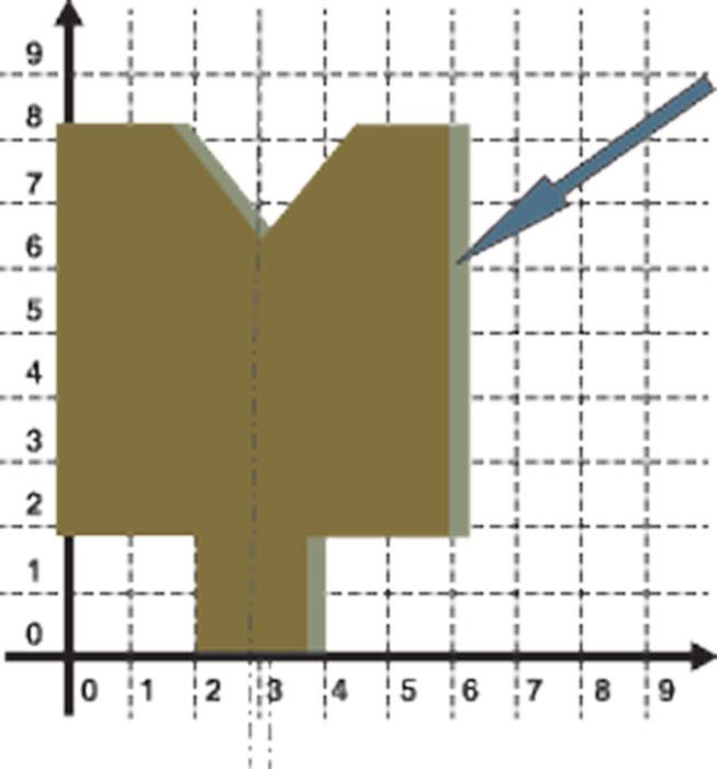
Figure 1
If a planer die is reversed on the brake bed, its center shifts.
Prepare the Tooling
Inspect your tools. Clean and dress off any apparent nicks and burrs that could affect the tooling’s performance. Look for obviously worn radii relative to the remainder of a given piece of tooling. Set those tools aside; you can’t use them. Those aren’t press brake tools anymore. Those are boat anchors.
Next, check all gooseneck tools with a straight edge to ensure they’re not bent (or “sprung”). Place the straight edge on the back of the tool; if you can “rock” the straight edge slightly, the tool is bent and no longer usable. That’s because its nose radius center will not match pieces from the same set. It’s also a safety hazard. A bent tool is a weak tool and is more likely to break and cause injury.
Planer Tools
Old machines are not designed to take advantage of precision-ground tooling; they’re really designed for planer tooling. Even modern low-end machines are normally designed to accept only planer tooling, though some machines do have adapters for modern tools.
Modern precision-ground tools are manufactured by gauging from the center of the tool. Planer tools are manufactured from an X-Y axis. Because they’re cut from an X-Y coordinate, they can be difficult to work with. Usually purchased in 10- to 20-foot lengths and then cut to size for specific projects, these tools are manufactured on a planer in lengths of up to 40 ft. with an error of 0.005 in. over 10 ft. Over 40 ft. that’s a total error of 0.020 in. For a tool purchased in a 20-ft. length, this would make the error 0.010 in. over the entire length.
Cut 6 in. off from one end of the die, reverse it, and it will not mate properly. You may not be able to see it, but there will be a few thousandths’ variation because you have moved the reference point (see Figure 2). And you certainly will not be able to mate that piece to the far end of the tool, where the variance will be even greater.
This applies to all planer punches and dies. As little as 0.005 in. in tool geometry variation can manifest as several degrees of bend angle variation. This variation needs to be adjusted for during setup. It also means that a staged tooling setup is almost impossible.
This does not mean that planer tooling has no place in today’s world. It very much does. It only means that you need to recognize and deal with the axis shift. For best results, keep projects within the limits of the tooling. This applies to both the punches and dies.
Establish the Origin Points
How does this axis shift affect the setup? Rather dramatically! When these tools are mounted on the press brake, the variations within and between tools cause the center of the radius to shift along the press brake’s X axis. This changes its relationship to the backgauge position.
Because the punch tip radius establishes the bend line at the center of the bend, you must set the stops or calibrate your backgauge to that center. You have two ways to do this; one is for manual or fixed stops and the other is for simple powered backstops.
Nonetheless, they both begin in the same way. Begin by bringing the ram to bottom dead center, its lowest point. Then adjust the opening to accommodate the punch and die set, leaving enough clearance to slide the tooling into position. Manually tighten the punch into the ram, center the die as close as possible, and tighten it down. Then seat the punch and die, bringing the tool set under a slight load and setting the tools firmly into the press brake.
Using the adjustment mechanism, raise and lower the punch into the die space while watching the die for movement. If the die moves, the punch is not centered in the die. Adjust and check it again, but bear in mind that if you adjust one end of the tool you will change the other, and it may take some back-and-forth adjustments to get it right. Do not skip this step. The tooling must be centered, especially if you are bottoming or coining with it.
Setting a Manual Backgauge
Measure the width of the entire die—not just the opening, but the entire body of the tool—and divide that value in half. Then add that number to the flat dimension from the edge to the bend line. Set your combination square to this number. For example, if the total die width is 2 in. and the flange is 3 in., your combination square needs to be set to 4 in.
Place the square against the die and, while holding it in place, move the stop against the end of the square and clamp it down. Do this for both stops. Note that, for safety reasons, this might require two people to perform.
At this point the two backgauges should be set to the dimension. Remember, though, rarely is it ever perfect, and you’ll no doubt need several setup pieces to tune it in, but that is the nature of the beast.
Setting a Powered Backgauge
If you are setting up a powered backgauge to planer or precision-ground tooling, you need to first physically unlock the backgauge, slide it completely to the end of its travel, and secure it there. Then find your gauge block.
Set the number wheels to the dimension from the center of the gauge block’s “V” to the end of the gauge, and send the backgauge to that setting. This places both gauge blocks firmly between the punch and die under a very slight load. Now, physically place the backstops against the end of the gauge blocks and lock them into position. Your backgauge is now calibrated to the center of the bend, and even a simple controller will be able to move the backgauge from position to position.
As a side note, while it’s not always possible, always try to program your forming order so the movement is toward the centerline. This makes the clearance inherent in the mechanism to work for you rather than against you.
Safety Considerations
Flywheel-driven machines are extremely dangerous. They move very fast, and they don’t back up. The average mechanical press brake can achieve up to 150 percent of the rated tonnage at the bottom dead center of the stroke. While some machines can move a backgauge in and out, none of these machines can control the ram reversal location. They have to make a complete stroke.
This, of course, has serious safety implications. In the U.S., this means that you need to close the ram to 0.25 in. above the material thickness before placing any part of your body within 4 in. of the pinch point. (Editor’s note: For more on proper safeguarding, check out “Know your press brake safeguarding options,” archived at www.thefabricator.com.)
Precision Planer Versus Precision-ground Planer
While planer tools definitely have their place and will be with us for some time to come, they have their limits. Machines designed for this type of tooling also can be fitted with precision-ground tools, which you can set up using gauge blocks; you just won’t need to do it every time you change a tool.
When you purchase planer tooling, pay attention to whether it is “precision planer” or “precision-ground planer.” Precision planer tooling is still planer tooling with all the same issues that any planer tooling has. Precision-ground planer tooling is precision-ground tooling cut to planer profiles.
You can decide which kind of tool is best for your operations; just account for the tooling’s limits. Also know that you often can form just as nice a product with planer tooling on older or simpler machines—just not quite as efficiently as you could on a state-of-the-art machine.
Steve Benson is a member and former chair of the Precision Sheet Metal
Technology Council of the Fabricators & Manufacturers Association International®. He is the president of ASMA LLC, steve@theartofpressbrake.com.
Benson also conducts FMA’s Precision Press Brake Certificate Program, which is held at locations across the country. For more information, visit www.fmanet.org/training, or call 888-394-4362. The author’s latest book, Bending Basics, is now available at the FMA bookstore, www.fmanet.org/store.
About the Author

About the Publication

subscribe now

The Fabricator is North America's leading magazine for the metal forming and fabricating industry. The magazine delivers the news, technical articles, and case histories that enable fabricators to do their jobs more efficiently. The Fabricator has served the industry since 1970.
start your free subscription- Stay connected from anywhere

Easily access valuable industry resources now with full access to the digital edition of The Fabricator.

Easily access valuable industry resources now with full access to the digital edition of The Welder.

Easily access valuable industry resources now with full access to the digital edition of The Tube and Pipe Journal.

Easily access valuable industry resources now with full access to the digital edition of The Fabricator en Español.
- Podcasting

In this episode of The Fabricator Podcast, Caleb Chamberlain, co-founder and CEO of OSH Cut, discusses his company’s...
- Trending Articles
1
AI, machine learning, and the future of metal fabrication

2
Employee ownership: The best way to ensure engagement

3
Steel industry reacts to Nucor’s new weekly published HRC price

4
Dynamic Metal blossoms with each passing year

5
Metal fabrication management: A guide for new supervisors
