


Precision sheet metal bending and the V groove: Part II
V-grooving: a tool bending
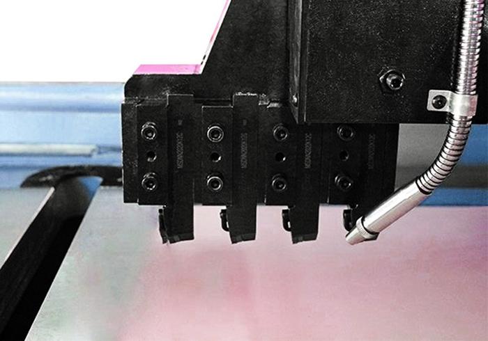
Figure 3
Multiple cutters in the V-grooving machine help reduce heat buildup.
Last month I introduced the concept of V-grooving, a viable option if you need to produce cosmetically critical bends with very tight bend radii. If you see an architectural panel bend with an outside radius that’s extremely tight for the material thickness—and it looks perfect, free of any trace of cracking—chances are it was formed with V-grooving.
V-groove bending can establish the bend line and bend angle using grooves cut along the bend line. It’s also known as score-folding, V-cutting, and back-scoring. The grooving process, performed by a separate cutting machine, produces a V-cut located at the bend line. After groove-cutting, the bend can be completed at the press brake or even by hand. At the press brake, the operator can bend the grooved metal into various angles and shapes using off-the-shelf or custom tools.
Last month I described the advantages, which include ease of forming and dimensional accuracy, and disadvantages, which include the low strength of a V-groove bend. This month I’ll cover exactly how to perform V-groove bends and how you can make the process as repeatable and reliable as possible.
The Groove Machine and Cutting Tools
If you’re thinking of using the V-grooving technique to produce parts, first think carefully about the application. V-grooving is used mostly in low-stress architectural applications, and the finished piece will be only as strong as the remaining thickness of material at the bend. V-grooving is not a process for all manufacturing situations.
If you choose to use V-grooving, you need to account for the radius reduction from the thinning of the material at the cut. Whether radius reduction is a good or bad thing just depends on the function of the part. For instance, V-grooving can start with 0.080-in.-thick material at the bend line and reduce it to 0.030 in. Generally, V-grooving reduces the thickness at the point of bend to between a third or half of the original thickness. Obviously, V-grooving is not for applications that require bend strength. Nevertheless, you can produce a very sharp corner without stress cracks on the outside of the bend.
Because V-grooving reduces the material thickness at the bend, it requires less tonnage to complete the bend. This means that thicker sheets can be bent with less forming tonnage.
The groove can be produced on a horizontal shaper machine, which uses linear movement to use a single point of a cutter to cut a path on a flat surface, like the way a lathe removes material from a cylindrical object. This allows for the forming of an extremely sharp inside bend radius without creating stress cracks on the outside of the bend and without the excessive tonnage requirements of a bottoming or coining operation.
Historically speaking, before V-grooving and modern CNCs teamed up, the little V-grooving that was being done used a machine shop planer to cut the V-grooves. But without a proper way to secure the sheet metal to the machine table, the V-groove depth was difficult to control and extremely inefficient.
More recently shops have relied on CNC grooving machines designed for the task. The accuracy of these machines is the same as any other CNC equipment, positioning within 0.005 in. on average. The machines place the cut or miter precisely on the bend line, with the correct cut angle that will create the formed dimension. They’re called various names, including CNC V-grooving machines, V-groovers, CNC V-cutting machines, or simply V-grooving machines.
In a modern CNC V-cut horizontal shaping machine, the sheet is positioned directly under a cutter. The controller’s program uses the material parameters (thickness, quality, etc.) to guide the depth and location of the cut. These machines look very similar to a modern laser or plasma cutter.
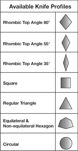
Figure 1
These are just a few of the cutter profiles available on modern V-grooving machines.
The knives (cutting tools) you insert in the machine will depend on the bend angle you need. For example, if you need the internal bend angle to be between 45 and 60 degrees, you’ll need a rhombic-shaped cutter with a 35-degree cut angle. If your internal bend angle is between 60 and 80 degrees, you’ll need a triangular cutter; and for internal bend angles between 80 and 90 degrees, the cutter should also have a cut angle between 80 and 90 degrees. Figure 1 shows the basic cutter shapes, but you also might need to fine-tune the knife angle to achieve the groove angle you need.
If you are a regular reader of Bending Basics, you know that the springback will need to be compensated for. When V-groove bending, you need to account for springback not only with the press brake tooling, but also the angle of the cut. In most cases, an extra 1 or 2 degrees in the groove cut angle can take care of it.
Sometimes, though, you’ll run across material types and bend angles that have significant springback, and you’ll need to cut a greater groove angle to deal with it. The larger groove provides clearance to ensure that the notch you cut won’t bind during forming. With the right punch tool angle, you should have only a minor gap in the V-cut between mating edges (see Figure 2).
The cutter angle you need equals the required angle of cut plus a small amount of additional cut angle to compensate for springback. This is usually calculated as half the degrees of the internal bend angle (so a 90-degree V-groove bend would give you a 45-degree cut angle) plus half the degrees of springback, if necessary.
Grooving Machine Operation
The cut depth and the remaining material thickness will vary by the design. Never try to produce the V-groove in a single pass. Instead, the groove cut should not exceed a depth of 0.031 in. per pass. This will make it necessary to use multiple passes to complete the cut and reduce burring at the cut line.
To prevent this, you can establish some default settings at the machine. As mentioned, the initial cut depth should never exceed 0.031 in. The minimum material thickness, as measured from the bottom of the V-groove to the bottom of the material, should be no less than 0.011 in. Using these default settings, you can adjust the depth of the cut according to the size of the material and style of groove required.
Consider an application where you need to make a 0.036-in. deep V-groove in 0.060-in.- thick material. You might make the first cut at 0.02 in., repeating the cuts by 0.020 in. until you almost achieve the final depth. You then make a final finish cut to an additional depth of 0.008 in. This leaves the remaining material thickness at the desired dimension. And because the final pass is a light finishing cut, if the knives are sharp, the resulting groove should be burr-free.
Heat Buildup
Heat buildup is a common factor in most cutting processes in sheet metal fabrication, and V-grooving is no different. If you V-groove by continually using the same knives or taking too deep of a cut, you can ruin the V-groove’s appearance and increase burring in the groove cut, just because the cutter is overheated and turning soft.
For material 0.078 in. or thicker, you’ll likely need to take multiple passes. Some material might require as many as eight passes to get the cut to its final depth.
To increase production, reduce costs, and slow any overheating, you need to use multiple knives. To mitigate the heat buildup, V-grooving machines can have multiple knives grouped next to each other on one head assembly (see Figure 3). If you have, say, four knives on the head, two cycles over the sheet would be the equivalent of eight passes. Each knife should cut the groove only a few thousandths deeper. And because each knife cycles over the material twice, you won’t get the same heat buildup as you would performing eight passes with a single cutter.

Figure 2
You can compensate for springback by changing the angle of the groove.
Developing the Flat and Bend Calculations
As you may have already guessed, developing the flat for V-groove bending is also going to be different, as will the resulting bend deduction. Whether you’re developing the flat manually for a prototype or modeling in CAD, to achieve accurate flat blanks, you need exact values to deduct for each bend.
To perform your bend calculations for a V-groove bend, take the difference between the thickness of the material and the depth of the V-groove cut and use it to perform the calculations.
For example, if your material thickness is 0.090 in. and your groove cut removes 0.060 in., you’ll use the remaining thickness of 0.030 in. to calculate the bend allowance and bend deduction. You’ll also run the calculations with the inside radius being the same as the material thickness—the “perfect” bend.
Rules for Operation
Operationally, V-groove bending and traditional forming have much more in common than you might think. And if you follow some basic rules, your experience with V-grooving will be a good one.
- At the press brake, take the time to center the punch into the die. Failure to do so will lead to dimensional issues, angular variations, and subsequent cosmetic issues.
You must air form V-grooved parts. Bottoming or coining will damage the workpiece and defeat the reason for V-grooving in the first place.
You need to maintain the TX axis and center it from end to end. The TX axis is the relationship between the center of the punch and die and the backgauge.
You also need to hold the TY axis. The TY axis is the parallelism between the punch nose and the forming die.
Select the appropriate bottom die based on the total material thickness (using the 8x rule) and not the radius or the sheet thickness at the V-groove. The radius is a function of the V-groove.
If you are bending across a series of holes in a piece of sheet metal, the material will tend to shift to the weakest point—in this case, the center of the V-groove. If any alignment issues are present, the workpiece will not bend correctly or consistently.
To avoid wedging the tools together, always use an acute profile punch and die set of 85 degrees or less.
Feeling V-Groovy?
If you’re thinking about using the V-grooving process, it might take you some time to achieve the necessary depth of understanding to apply all the possibilities the process allows. While useful, V-grooving is not for every application or project. For some parts, the strength of the bend is essential to the function of a component, so they require the full material thickness and larger bend radii to maintain the necessary strength.
That said, for bends that will become architectural surfaces in low-stress applications, V-grooving sheet materials offers some unique options:
It creates decorative grooves and channels.
It can help create architectural shadow gaps.
It allows for sharp bends.
It forms profiles that have the appearance of solid or extruded material.
You also can experiment with different cutters to groove different shapes, including wider V’s, half circles, and squares. These allow for a range of design variations where traditional bending methods simply can’t meet the forming requirements.
The technology has found a home in certain sectors, especially in architectural fabrication. Will this novel approach become a mainstay in other areas of the sheet metal industry? Only time will tell.
Steve Benson is a member and former chair of the Precision Sheet Metal Technology Council of the Fabricators & Manufacturers Association International®. He is the president of ASMA LLC, steve@theartofpressbrake.com. The author’s latest book, Bending Basics, is now available at the FMA bookstore, www.fmanet.org/store.
About the Author

About the Publication

subscribe now

The Fabricator is North America's leading magazine for the metal forming and fabricating industry. The magazine delivers the news, technical articles, and case histories that enable fabricators to do their jobs more efficiently. The Fabricator has served the industry since 1970.
start your free subscription- Stay connected from anywhere

Easily access valuable industry resources now with full access to the digital edition of The Fabricator.

Easily access valuable industry resources now with full access to the digital edition of The Welder.

Easily access valuable industry resources now with full access to the digital edition of The Tube and Pipe Journal.

Easily access valuable industry resources now with full access to the digital edition of The Fabricator en Español.
- Podcasting

In this episode of The Fabricator Podcast, Caleb Chamberlain, co-founder and CEO of OSH Cut, discusses his company’s...
- Trending Articles
1
AI, machine learning, and the future of metal fabrication

2
Employee ownership: The best way to ensure engagement

3
Steel industry reacts to Nucor’s new weekly published HRC price

4
Dynamic Metal blossoms with each passing year

5
Metal fabrication management: A guide for new supervisors
