


Press brake bending tips for forming tapered bends and determining minimum flange lengths
When reviewing the basics, operators and engineers should work with, not against, each other
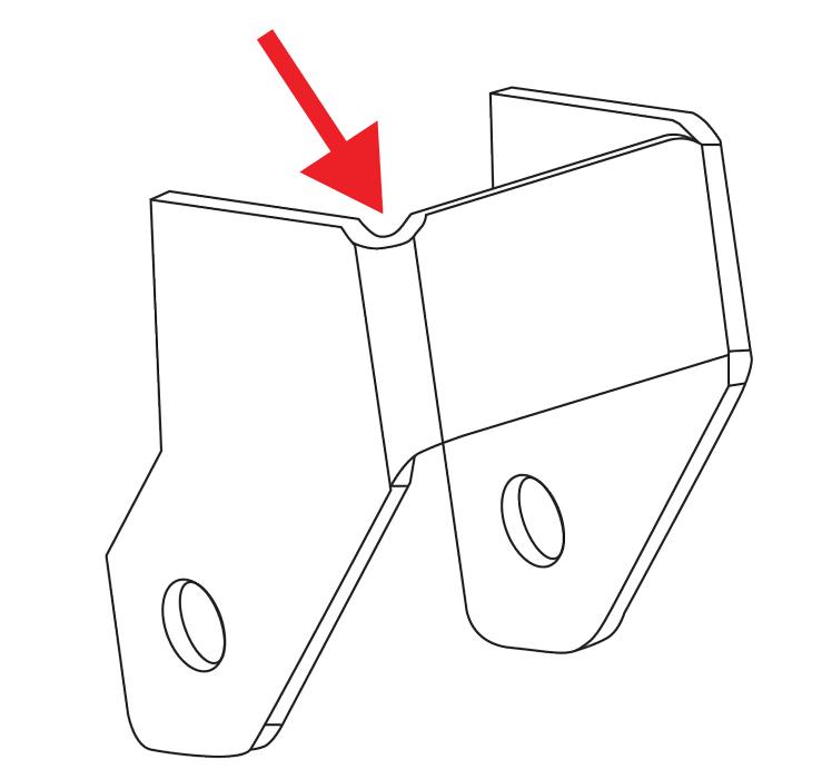
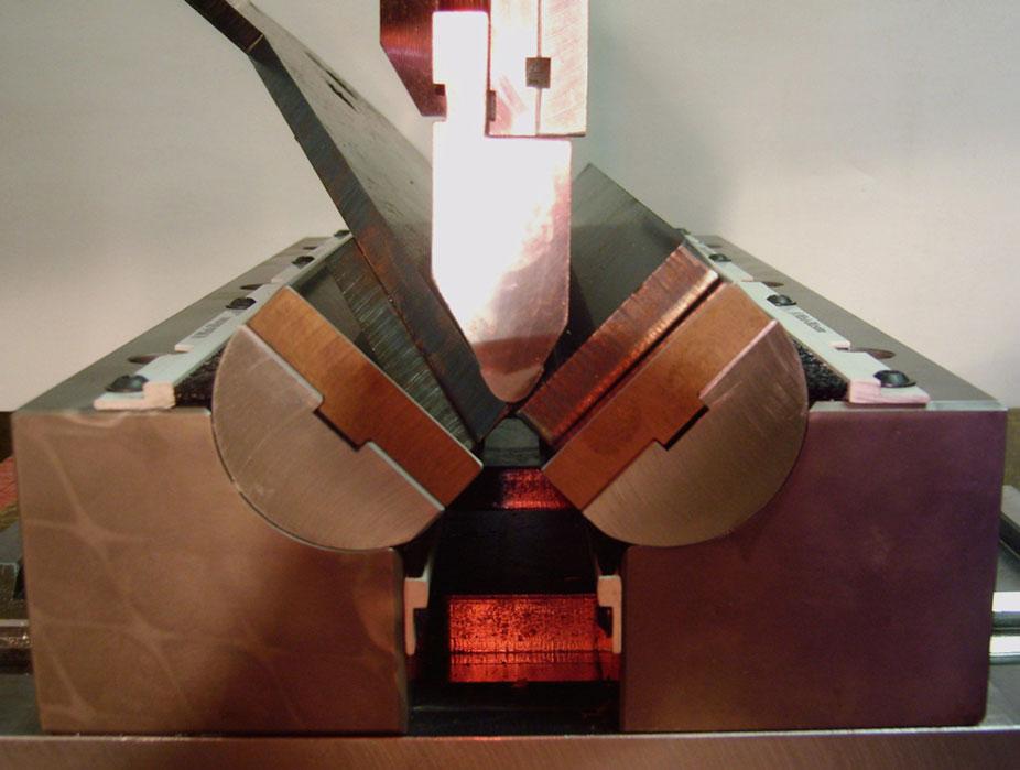
Figure 1
The relief shown mitigates the distortion (“convexing”) that occurs at the end of bends.
Questions: Thanks so much for your helpful articles. I have four questions. First, bend charts list a minimum flange length, but is there a formula that can be used for a minimum dimension as it relates to the overall feature length to prevent distortion in holes, for example? I have been using the minimum flange length on bend charts as a conservative distance.
Second, is there a proper way to design relief cuts near bends and a good way to determine when exactly they are needed (see Figure 1)?
Third, I have numerous parts with edges that run at an angle across the V opening; that is, the flat part dimensions are not perpendicular to the bend line (see Figure 2). This tends to twist the part in the die. Is there a way to avoid this?
Fourth, do you cover this type of information in your classes? Any further details about your approach to training would be much appreciated.
Answer: These are some great questions, covering everything from flange lengths to relief cuts. So without further ado, let’s get started.
Minimum Flange Lengths
The minimum flange that can bend comfortably in any given die width is equal to 70 percent of that die width for a standard V die and about 110 percent or more of the opening for an acute die. This keeps the flange from snapping into the die space. Following this rule, you should be able to place the workpiece on the die so that the material contact on the die shoulder equals 20 percent of the die opening (see Figure 3). This is a good and safe rule to follow.
Still, the amount of workpiece contact you need depends on the die radius. If you have a sharp die radius, common in precision-ground tooling, you should be able to safely lower the percentage to 10. Alternatively, many traditional tools have a die radius that’s either a large single radius or a compound radius. A compound die radius increases as it goes into the die opening. In these cases, you may need to increase the percentage beyond 10.
Know that dies with either a large radius or a compound radius help reduce or eliminate die marking on the workpiece. A sharp die radius is going to leave marks.
It is possible to “cheat” the bend by using a smaller die opening or offsetting the punch and die centers. But this rarely works well in a production environment. Besides, offsetting the punch and die centers can be dangerous. You could seriously damage the tooling, the press brake, and yourself.
Bend Reliefs
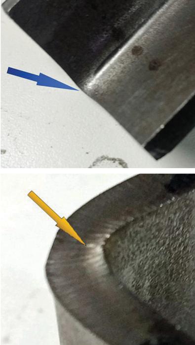
There are no hard-and-fast rules as to which style of relief to use. The radius style relief you show on your drawing will work fine. Bends often will “convex” at the end (see Figure 4), so I would apply the relief to parts that have to mate with other parts and where convexed material could interfere with the assembly of a unit.
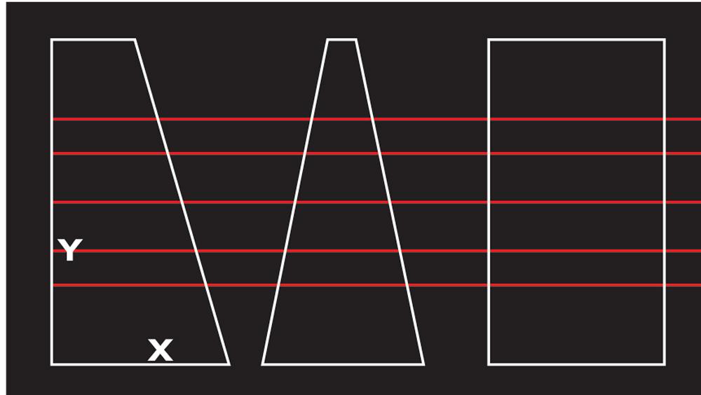
Figure 2
Here three blanks are positioned over a die, with the red line in the center being the bottom of the V. The blanks on the left and center have tapered bends and have the potential of twisting and pulling during the bend cycle.
There are a couple of things to consider when you use a rounded cut to relieve the end of a bend. First, if you are using a punch press, never make the cut diameter smaller than the material thickness; this helps you avoid bending or breaking the punch. For best results, produce the relief by using a punch diameter equal to the bend deduction.
Side gauging also can be affected by this convexing, as the side gauge interacts with the convex area of the bend. Specifically, the convex area pushes against the gauge, shifting the overall part position, which of course doesn’t help your gauging consistency. To avoid this, make sure the side gauge is thinner than the material thickness. As you can see in Figure 4, the convexing occurs at and near the surface of the inside radius. If you use a thin side gauge that touches only the lower portion of the material thickness, you can resolve those gauging errors and inconsistencies.
Tapered Bends
There are many possible definitions for tapered bend, angular and dimensional. For our purposes here, a tapered bend is one that will pull and taper during forming because the edge is angled--that is, not perpendicular to the bend line. A tapered flange is one in which the bend line dimension is deliberately produced.
Forming such bends can be a challenge. Your piece with symmetrical angled edges (the center blank in Figure 2) also can form unevenly. This occurs as the workpiece twists and pulls in one direction as it is dragged into the die space.
The larger your die width and the more uneven the part edges are, the more substantial the chances of pulling will become. You are correct that a smaller die opening sometimes will help, but at a cost—tool marks on the part.
How you overcome this problem depends on the application, and many options are case-specific. You can use a side gauge, especially for a part with at least one square edge. Beyond this, you have three other options.
Option 1: Good. Use a backup, either rectangular or square, made from a material of the same type and thickness as the workpiece. You place the workpiece on top of the backup and bend them both together, treating the workpiece and backup together as “one” material thickness. You need to choose a die width and run your bend calculations based on that new thickness.
Using backup material of the same type and thickness puts the outside surface of the workpiece at roughly the neutral axis of the two materials’ combined thicknesses. This makes the workpiece’s outside surface undergo the least distortion.
Also make sure the grain direction in the backup material is the same as the grain direction in your workpiece, preferably oriented for bending across the grain rather than with the grain. This will help you achieve a consistent bend angle from piece to piece.
Wrapping or backing up the part works well to reduce distortion around features close to or on the bend line. You’ll still see some distortion on holes and other features, but it will not be nearly as bad as when forming without the wrap.
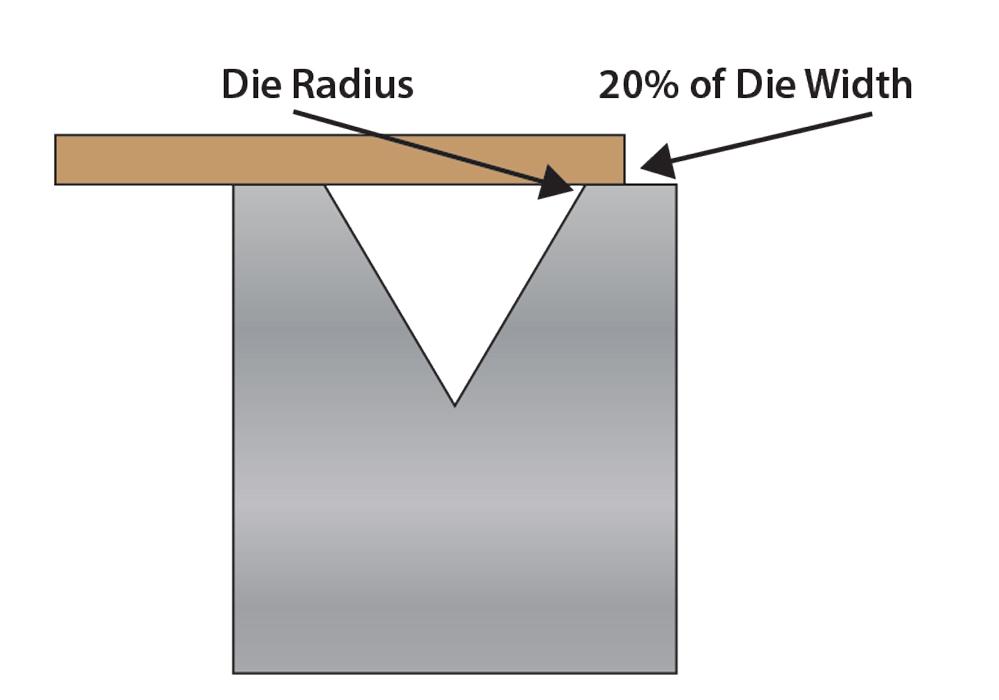
Figure 3
In determining a minimum flange length, you should be able to place the workpiece on the die so that the material contact on the die shoulder equals 20 percent of the die opening
All in all, this is a slight improvement over using a single side gauge for a part with double tapered edges. It’s also excellent for controlling feature distortion, which, incidentally, also can cause the bend to taper.
Option 2: Better. This involves laser stitching, in which material attached to the workpiece is held on by shaker tabs or microjoints. The extra material squares the part and reduces or eliminates pulling during bending. The operator then simply snaps off the extra material and, if necessary, files the tab joints. If pulling still occurs, you can introduce an opposing taper in the add-on material to compensate.
While not perfect for this application, this method does work. It also solves other gauging problems, like when forming a part with no square edges to gauge off of.
Option 3: Best. Your best choice is a winged-style, or rotational, die (see Figure 5). These dies work differently from the standard V die. Rather than the part being dragged down into the open die space (which can cause the bend to taper), the part remains static while the die moves around the workpiece. The winged die allows a tapered bend to be made without pulling or distorting. This tool type also will reduce distortions that come from a feature being on or too close to the bend line.
About Operator Buy-In
I have presented sheet metal training programs for the last 23 years as the Fabricators & Manufacturers Association’s exclusive press brake trainer. While press brakes are my expertise, my training is not exclusive to them. I can tailor a program to your specific needs as a one- or two-day in-house program for your engineering department, a two-day program for your technicians, or both.
I bring the floor folks into the discussion here because much of what is necessary for quality and consistent production requires the operator to buy in to the processes, especially when it comes to forming on the press brakes. As all press brake operators are prima donnas (I kid here, of course … for the most part), having their buy-in can make or break the entire training effort.
My primary training objective is to get the operators and engineers speaking the same language. They should work together rather than oppose each other.
To that end, I have the engineers go to the shop floor and, without judgment, find out what methods the brake operators use with which material types. Engineers complete a list of the available tooling types, styles, profiles, radii, die and punch angles, and die widths. I then go back and design parts to match the realities and processes of the shop floor.
By asking the operators for their input, you have the added benefit of their buy-in. Say you develop a workpiece to be air formed on a specific die set, which is necessary for achieving the inside radius and bend deduction. When you send the job to the floor and inform the operators that they must air form using a 0.551-in. die opening, they will. Why? Because the information originated with them.
Steve Benson is a member and former chair of the Precision Sheet Metal Technology Council of the Fabricators & Manufacturers Association International®. He is the president of ASMA LLC, steve@theartofpressbrake.com. The author’s latest book, Bending Basics, is now available at the FMA bookstore.
About the Publication

subscribe now

The Fabricator is North America's leading magazine for the metal forming and fabricating industry. The magazine delivers the news, technical articles, and case histories that enable fabricators to do their jobs more efficiently. The Fabricator has served the industry since 1970.
start your free subscription- Stay connected from anywhere

Easily access valuable industry resources now with full access to the digital edition of The Fabricator.

Easily access valuable industry resources now with full access to the digital edition of The Welder.

Easily access valuable industry resources now with full access to the digital edition of The Tube and Pipe Journal.

Easily access valuable industry resources now with full access to the digital edition of The Fabricator en Español.
- Podcasting

In this episode of The Fabricator Podcast, Caleb Chamberlain, co-founder and CEO of OSH Cut, discusses his company’s...


