


Bending Product Manager
Years ago an operator might install a single punch and die set on a press brake and keep that tooling setup for days, even weeks. It exemplified the traditional view of production efficiency at its finest.
But shrinking order sizes and lead times changed everything. A custom fabricator now might need to run 20 or more different jobs on the press brake over one shift, with many if not all calling for different tools—and all the changeover time that comes with them. Fabricators rarely can afford such inefficiency in time or labor.
Bending complex parts creates just as many challenges. With multiple bends requiring different tool sets, complex parts require that much more labor, setup, and teardown time.
How do fabricators gain efficiencies when forming complex parts or a series of different parts, all of which require multiple tooling setups? In these cases, fabricators turn to stage bending, in which multiple tool sets (punch and die combinations) are staged next to each other across the press brake bed.
Operators can complete a complex part on one machine in one setup. They can also use one setup to bend a variety of parts—five parts here, three parts there, a dozen parts after that—each using some combination of the tooling across a single press brake bed.
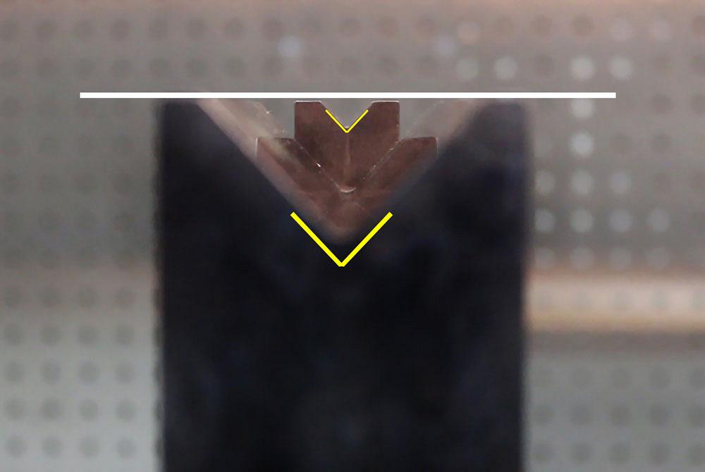
The practice has become common at many shops, where skilled press brake operators regularly work through various staged tooling situations. But the task isn’t as straightforward as it sounds. It doesn’t just happen by arranging sectionalized tools across the press brake. A staged setup must allow an operator to remove a part after each bend, without damaging the part. Then comes the most critical factor: shut height, or the space between the brake bed and ram at the bottom of a bending stroke for a particular job (see Figure 1). For staged bending to work, all tool sets must perform their intended task at the same shut height.
Considering all this, how do press brake setup technicians and operators create these setups so they can perform staged bending efficiently and effectively? They have several options.
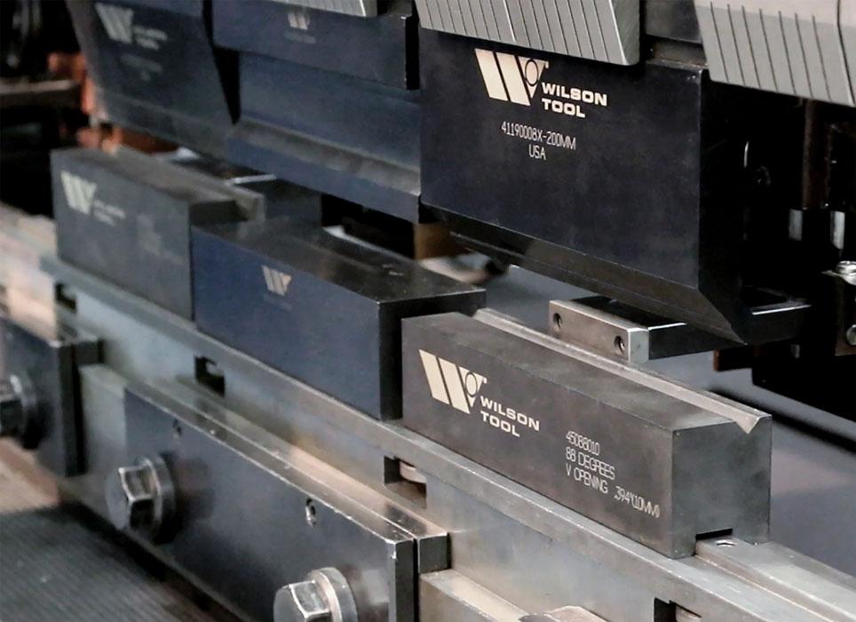
Say an operator has one 90-degree tool set and then another 90-degree tool set with a different V opening, side by side. This assumes the bend line is short enough to load both tool sets in the brake at the same time. To form the second 90-degree angle in the larger and deeper V opening, the punch tip descends slightly farther (see Figures 2 and 3). This creates a deeper stroke that, if not accounted for, would cause the first tool set to collide, damaging both the tools and the press brake and creating a serious safety hazard for anyone nearby.
To avoid this, operators use the oldest trick in the book: shimming. Specifically, they insert a makeshift shim or riser under the tool set with the larger and deeper V opening, so that it shares a common shut height with the first tool set (see Figure 4). This allows the operator to load both tool sets at the same time in a setup that prevents the tooling from colliding.
While seemingly simple, using shims and risers can be quite complex, requiring time and significant operator skill. What’s more, each setup might require different-sized shims or risers because of different tooling required to reach the common shut height. This means that each setup could require individual shimming for each part. This is more common on some tooling types than others. Regardless, it can wreak havoc on lean practices and often causes so much downtime that it’s faster to form the parts in multiple, simpler setups.
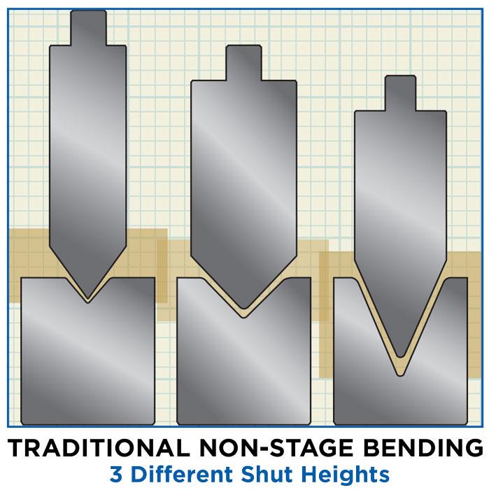
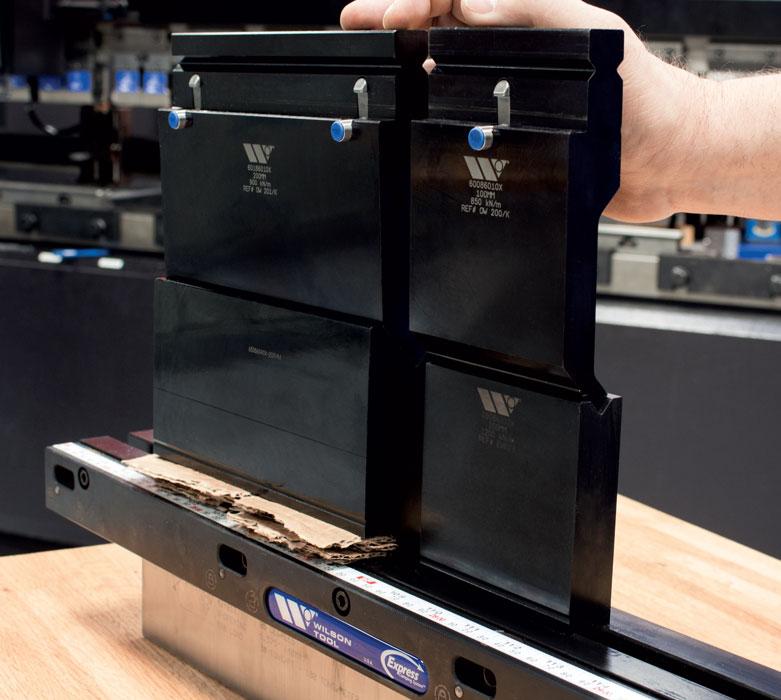
Figure 1
These tools have three different shut heights and, as such, could not be used together for staged bending without manual adjustment.
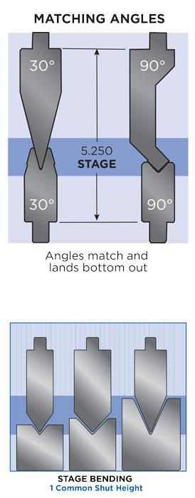
Normally viewed as a middle-of-the-road solution, this type of stage bending uses tools from the same punch family along with the same angle and same V opening (see Figures 5 and 6). The die and punch angle in each tool set must match. For instance, one staged setup might have a 90-degree die mated with two 90-degree punches.
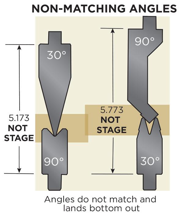
The punches must be from the same theoretical sharp height family (see Figure 7). As long as operators match the tooling in this way, they can perform staged bending. If the punches are from the same height family but the angles do not match, or if the die V opening is changed, the dies are not staged to bottom out at the same time.
This is certainly more efficient than shimming. Still, different part runs rarely use the same V opening and punch angle. This arrangement offers no flexibility outside a single tool family.
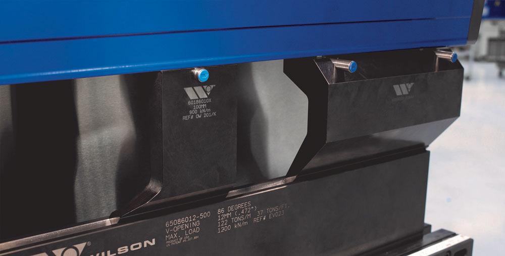
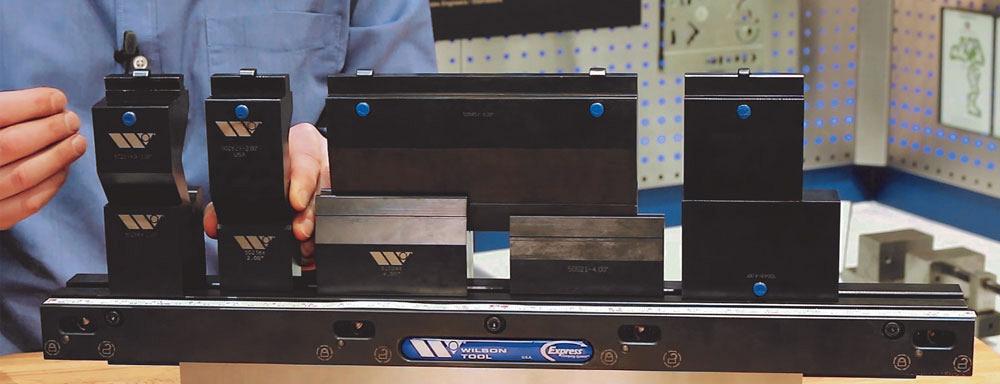
Tools designed with common shut heights eliminate the need for shims and risers and offer more flexibility than tool sets with the same die and punch angles (see Figures 8 and 9). The design of staged tools (also known as common-shut-height tools) allows for multiple punch and die sets to be set up in a single press brake. With staged tools, a single setup can have a mix of angles, offsets, flattening tools, even gooseneck punches and dies with different V openings. After loading the tool sets, operators handle the part blank once, carrying it in a sequence from one tool set to the next.
Stage bending can lead to leaner practices, but as with anything else, a fabricator first needs to consider the application variables. This includes the part geometry. If a part is as long as the press brake, an operator will use just one set of tools. In this case, staged bending obviously isn’t possible. The part geometry just doesn’t allow for multiple tool setups.
Another factor is the number of different tool profiles a job requires. Say a job requires many tool profiles that would traditionally require multiple tool changeovers. If a fabricator has staged tooling, stage bending would be the obvious way to go. In a stage bending setup, an operator could make all the bends for one part without having to change or handle tooling.
But what if a shop doesn’t have such tooling? If a job requires numerous tool profiles, stage bending using old-school shimming methods still might make economic sense. It depends on numerous factors, including part quantity, order frequency, how long shimming takes, how repeatable the staged setup is, as well as how much changeover time the staged bending setup would eliminate.
A press brake usually performs bends with a single tool set in the center of the brake bed, where forces are equal and bends are true. Creating bends at the center of the brake gives operators the benefit of balanced forces.
Stage bending often applies bending forces not just to the center, but also on the left and right sides of the press brake bed as the operator moves from one tool set to the other. This brings up another consideration: To perform staged bending, a press brake should allow for off-center bending.
In general, downacting press brakes can accommodate unbalanced forces better than upacting brakes, as the downacting systems are equipped for compensating tonnage on the left or right side of the machine. Specifically, a downacting press brake has hydraulic cylinders to the left and right of the beam. Via the machine control, these commonly compensate for tonnage on the left or right side of the machine and allow off-center bending without causing the machine to shut down.
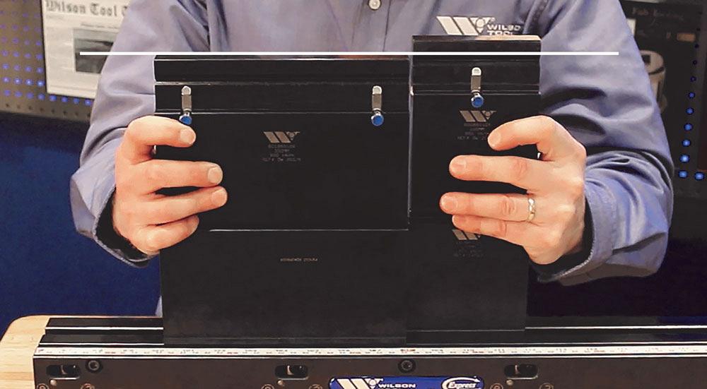
Figure 2
The tool set on the left has a die with a deeper V opening. These tools couldn’t be staged without shimming.
Upacting press brakes, however, have mechanisms that shut down the machine when too much tonnage is detected off-center. This isn’t to say that off-center bending couldn’t be done in an up-acting brake, but the application would have bend length and tonnage limitations.
When producing more parts more frequently, stage bending provides greater efficiencies. It also can benefit other quantity and frequency scenarios—a certain complex job ordered in low quantities but produced frequently, for example.
It’s all about scrutinizing the non-value-added time, including downtime from long changeovers and excessive material handling. Less is best.
Modern CNC press brakes have programmable backgauges. They move immediately from tool set to tool set, precisely gauging one bend after another. The modern multiaxis backgauge has made stage bending more flexible than ever.
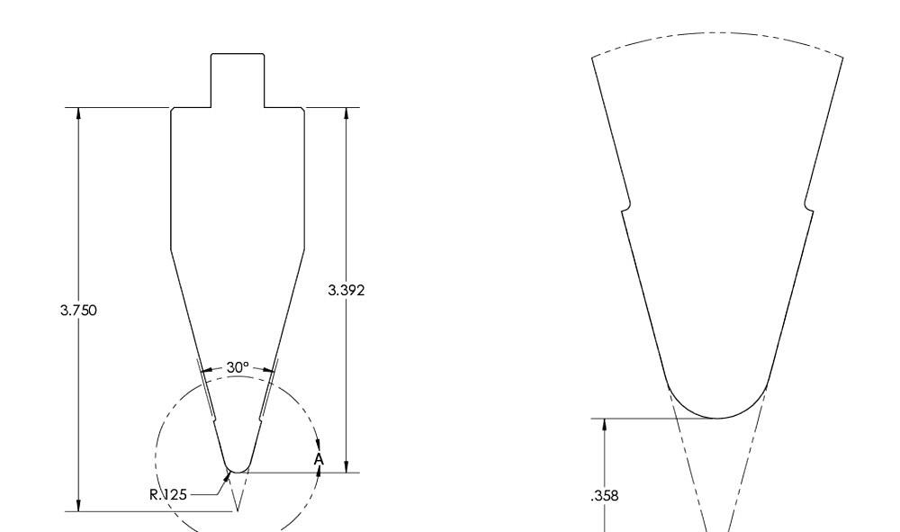
Gauging on old, pre-, or non-CNC machines is another story. The backgauge’s R axis—that is, the up and down motion of the backgauge fingers—poses the greatest challenge. The backgauge must be positioned on the R axis so it can gauge at different die shoulder heights (see Figure 3), where the operator places the blank over the die before initiating the bending cycle.
To adjust the backgauge on non-CNC press brakes, the operator turns a hand crank. Regardless, turning a hand crank usually doesn’t take much time. And fortunately for pre-CNC press brake operators, the backgauge adjustments usually are minimal or unnecessary, as long as the die shoulder heights are similar. With a few exceptions, most pre-CNC press brakes support stage bending if the die shoulder height varies slightly, as long as the backgauge is set to a midpoint.
As bending technology progresses to meet the needs of short-run, flexible manufacturing, stage bending has become even more pervasive. Offline bend programming and 3-D simulation can show a programmer exactly how a part will form from one tool set to another. Moreover, if a previously formed flange will collide with an adjacent tool, the programmer will see it before the job reaches the press brake.
The brake’s modern controller shows a 3-D simulation that guides the operator through the bending sequence. Some press brakes have foot pedals that move to where the next bend occurs, and others have LEDs just above the tooling that show exactly where the operator should go for the next bend.
Still, even on older machines, staged tooling can save significant time and money. While the old-school practice of shimming is still common and effective, fabricators have other stage-bending options. One solution is using punches of the same height and angle with the same die; another solution is staged tooling.
Ultimately, it’s about saving time by eliminating non-value-added material handling and changeover time—the classic wastes of lean. Common-shut-height tooling allows fabrication shops to stage-bend with both American- and European-style press brakes and multiple tooling styles to perform each bend required for a job. Put simply, stage bending allows a fabricator to get it done in one.
Steve Brown is press brake product manager at Wilson Tool International®, 12912 Farnham Ave., White Bear Lake, MN 55110, 866-286-6000, www.wilsontool.com.

The Fabricator is North America's leading magazine for the metal forming and fabricating industry. The magazine delivers the news, technical articles, and case histories that enable fabricators to do their jobs more efficiently. The Fabricator has served the industry since 1970.
start your free subscription
Easily access valuable industry resources now with full access to the digital edition of The Fabricator.

Easily access valuable industry resources now with full access to the digital edition of The Welder.

Easily access valuable industry resources now with full access to the digital edition of The Tube and Pipe Journal.

Easily access valuable industry resources now with full access to the digital edition of The Fabricator en Español.
In this episode of The Fabricator Podcast, Caleb Chamberlain, co-founder and CEO of OSH Cut, discusses his company’s...


