


General Manager
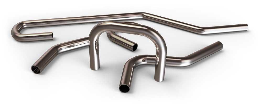
Figure 1
Even using the latest CNC technology, you need to understand how tooling and its placement can help to deliver repeatable, high-quality bends. This is particularly true with challenging applications involving expensive material. No one is a fan of excessive scrap.
Even though we are in the age of CNC machinery, the old phrase “the tools make the bend” is as relevant today as ever.
As tube bending applications have become more extreme (see Figure 1), tooling design, setup, and maintenance have returned to a position of central importance. In rotary draw bending, four simple setup steps, executed precisely and in the correct order, will help you maximize bend quality, tool life, and process control.
Many tube bending machine operators rely on machine features more than they should. Modern features on tube benders, especially pressure-die assist, permit many operators to obtain adequate results without mastering tooling setup. Many controls on CNC bending machines were devised to make difficult applications practical. Many operators use these controls to overcome the limitations of poor setup practices on routine applications.
This over-reliance on the machine’s controls “squeezes” the tube into the desired shape through use of excessive radial force at the point of bend. Because this approach works against the axial tension on the tube, it requires increased machine pressure to force the part into shape. This results in a trade-off: The tube is in the desired shape, but high pressure at the point of bend decreases tool life, process control, or both.
It is not necessary to sacrifice tool life or process control for better bend quality. You can maximize all three of these objectives with a little time and effort. It’s a matter of using a four-step procedure that precisely positions the tooling:
The trick to implementing the four-step setup successfully is understanding that each step addresses just one aspect of bend quality.
Accurate mandrel nose placement ensures a stable round cross section throughout the arc of the bend. A correct direct (or radial) pressure setting of the pressure die prevents buckling on the inside radius. A wiper tip properly raked away from the line of tangency prevents the wrinkle or series of small wrinkles that can form at the terminal end of the inside radius. And, finally, a balanced pressure-die assist setting pushes the outside radius sufficiently to mitigate flattening and to eliminate any terminal hump. Figure 2 illustrates the roles each factor plays in a tube bending application.
Not all draw bending applications require a mandrel, a wiper, or the pressure-die assist feature. However, understanding each of them can help you troubleshoot problems more accurately and quickly and determine the need for one of these if it is absent. Furthermore, taking these steps in the right sequence helps overcome a common troubleshooting hurdle: One tool improperly set up can mask another.
he mandrel is the central tool in the draw bending setup. It is your primary means of controlling the flow of tubing material at the point of bend. To determine the best placement of the mandrel nose, it is necessary first to understand the difference between the line of tangency and the point of bend.
The line of tangency is a theoretical plane fixed in space. It is perpendicular to the plane of bend and divides the bend arc from the tangent. Alternatively, the point of bend is an indefinite region surrounding the line of tangency in which the tubing material is in a
As the clamps draw the tube around the bend die, the tube wall thickens along the inside radius (intrados) and thins along the outside radius (extrados). The purpose of the mandrel nose is to cover this region of flowing material and ensure a consistently round cross section by mitigating the simultaneous compressing and stretching of the tube wall.
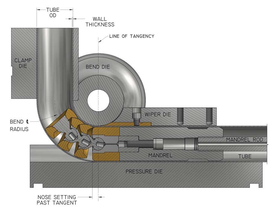
Figure 2
Understanding the basics of draw bending and how factors such as a mandrel, a wiper, or the pressure-die assist feature influence the bend can help you troubleshoot a tube bending application.
Because the point of bend extends past the line of tangency, so too must the mandrel nose to support it. If it does not, it will not provide the necessary control over the tube wall. The result is buckling and excessive flattening.
While more direct pressure from the pressure die often can prevent buckling along the inside radius, this makes another problem worse: It increases the drag on the outside radius, exacerbating the flattening of the outside radius. Therefore, placing the mandrel nose past the line of tangency is critical, because proper placement eliminates buckling and minimizes flattening.
Several factors come into play in calculating proper mandrel placement:
Using the Pythagorean theorem, you can calculate this maximum depth (b):
For instance, if the tube bend is a 2-inch tube diameter by 0.049-in. wall thickness by 4-in. centerline radius made with a standard-diameter mandrel, then the maximum depth is more than 0.625 in. Usually, a placement somewhere between one-half and two-thirds of the maximum is best. The less rigid the material, the deeper the placement must be.
This executes the forward mandrel principle of this setup procedure. After this first step, you should have a bend that has a consistent cross section throughout most of the arc. The most serious problem you might have is buckling throughout the inside radius.
If your mandrel nose is stable at the proper depth past the line of tangency and its diameter is not undersized for the application, then go on to the next step to determine the correct direct pressure-die setting. It is important to ensure that your mandrel nose is not undersized for the bend you want to make. There is a practical limit to how small a mandrel nose diameter can be and still be effective.
A properly sized mandrel nose is critical to mitigating flattening on the outside radius of the bend and buckling on the inside radius. The formula for a standard nose diameter (m) is:
If ease of loading is an important consideration, then the standard diameter (m) can be reduced by 0.005 in. for every inch of tube diameter (d). But if your mandrel nose diameter is substantially smaller than this, deeper placement of it past the line of tangency will not sufficiently compensate for its undersized condition. Buckling and flattening will occur.
If you have other problems such as terminal wrinkles on the inside radius or a terminal hump on the outside radius, continue on. These problems will be fixed later in the setup.
Because a properly set mandrel does most of the work in controlling the shape of the tube during the bending process, the pressure die’s job is merely to keep the tube in place. In other words, it should apply just enough pressure to prevent the tube from pulling away from the bend die during the bend. (If it does pull away, the inside radius will buckle into the gap created.)
Whether it is mechanical or hydraulic, the pressure die applies a radial force against the tube at the point of bend. Because this radial force is perpendicular to the natural axial flow of material in the draw bending process, drag results.
Too much drag results in terminal humps and excessive flattening of the outside radius. Too much drag is usually the culprit when the tube slips from the clamp dies. Thus, the objective is to eliminate as much drag as possible by determining the lowest amount of direct (radial) pressure needed to prevent buckling.
Most round tube applications up to 3 in. in diameter, whether mild steel, stainless steel, aluminum, or copper, require just 400 to 1,200 pounds per square inch (PSI) of direct pressure to accomplish this. Square and rectangular tubes (especially if bent the hard way) require higher pressures, and so do copper-nickel, superalloys, and some stainless steels.
No simple formula exists for calculating the optimum setting for every shape and material, but a little experimentation will yield substantial benefits.
For a typical 3-in.-capacity machine, use the following guidelines:
If continuous wrinkling or a buckle forms on the inside radius, increase the direct pressure setting in increments of 10 to 20 KSI until the problem disappears. If the inside radius has no noticeable deformation, consider dropping the direct pressure. After you determine the minimum direct pressure for the application, you can use it as a suitable reference point for future setups of the same application and a guideline for other applications.
This concludes forward mandrel and low pressure-die concepts. Remaining imperfections, such as a terminal inside radius wrinkle or terminal outside radius hump, likely will be remedied by the last two steps of the setup procedure.
The wiper’s job is to prevent a wrinkle from forming at the end of the bend. If no wrinkle appears at the terminal end of an otherwise smooth inside radius, a wiper is unnecessary. Skip this step and proceed to Step 4.
The wiper fills the gap behind the line of tangency between the inside edge of the tube and the curve of the bend die cavity. If the tube wall is not sufficiently rigid, it will bulge outward to fill this gap. With enough pressure on the direct pressure die, this bulge will flatten out between the bend die cavity and the mandrel nose as the tube is drawn through the line of tangency. But, at the end of the bend, if the bulge is not drawn through and flattened, it can form a wrinkle or a small series of wrinkles. Properly set, the tip of the wiper will catch the top of this terminal bulge before it sets into a wrinkle.
First, find the natural resting position of the wiper at zero rake; then determine the maximum rake for that application. To do this, hold a straightedge at the bottom of the grip section of the bend die cavity. With the wiper loosely mounted on the wiper post, bring in the wiper so that the bottom of its cavity also lines up with the straightedge. The wiper is now at zero rake. To find its natural resting position, gently slide the wiper along the straightedge toward the line of tangency until you meet some resistance. Determine if the feathered edge of the wiper tip is in complete contact with the bend die cavity. If so, you have found the natural fit. If not, apply slightly more force until the feathered edge is securely backed by the bend die cavity.
If you must use considerable force to find a fit, most likely the wiper is improperly cut, or you are trying to get the tip too close to the line of tangency. The latter is a common problem because it looks better when the wiper is at the line of tangency; however, most wipers are not cut to permit such a setting, nor is it necessary if the purpose of the wiper is limited to containing the terminal bulge.
Once you have found the natural zero rake position, rake the wiper by rotating the tip along the bend die cavity away from the line of tangency. You can increase rake in this manner so long as the terminal bulge does not set into a wrinkle. Once you have set the rake, you can measure the linear distance along the bend die cavity from the wiper tip to the line of tangency. Provided that replacement wiper tips are of the same design and manufacture, you can short-cut this step in the setup by setting a new wiper at this distance.
Note that raking the wiper applies only to low-pressure bending applications. Also, if the wiper is raked, the feathered edge should be cut to “simple-sweep” geometry. This is the most common geometric form. High-pressure jobs require zero rake and a feathered edge with offset geometry, not simple-sweep geometry.
Like the wiper, pressure-die assist is not always necessary. Its job is to prevent terminal humps and excessive flattening along the outside radius. If the outside radius is acceptable, you do not need pressure-die assist. Turn it off or set it to a neutral pressure, depending on your machine. Otherwise, start from neutral pressure and increase the assist until the flaws disappear.
Keep in mind that many CNC tube bending machines have both assist pressure and boost pressure. The term boost generally means a type of axial pressure applied during the bend to the entire circumference of the tube by means of clamps behind the pressure die. Using this type of pressure forces material through the line of tangency to feed both the intrados and the extrados. Assist, on the other hand, feeds material only into the extrados, which is useful in decreasing flattening and wall thinning.
An important advantage of the four-step setup procedure is that it facilitates troubleshooting. Most defects in a tube bend can be traced to the setup, and most setup defects correlate with a problem in one of the four steps. Therefore, after you have identified the nature of the defect, you will have a specific setup parameter you should examine first.
Ovality (i.e., general deformation of the tube’s cross section) is excessive. Check if the mandrel nose is undersized or not placed deep enough into the bend. If undersized, a temporary fix may be to advance it deeper into the bend. However, optimal bending will require a new mandrel made to the correct nose diameter.
The inside radius buckles. Check if the mandrel nose is placed behind the line of tangency. If so, advance past tangency according to the directions in Step 1.
The outside radius collapses. Check if the mandrel nose is placed behind the line of tangency. Advance past the line of tangency according to the directions in Step 1.
A hump or humps form on the outside radius. This is usually not because the mandrel nose is too deep into the bend, but because there is excessive drag or insufficient assist from the pressure die. However, if you do suspect the mandrel nose is the problem, check the depth of its placement, and compare it to the formula in Step 1. If the mandrel nose placement is too deep according to this formula, retract it.
Drag is excessive. This is not a defect but an immediate cause of many defects. Too much pressure from the direct pressure die is usually the culprit, but an oversized mandrel nose also can be the problem. Check if the mandrel nose diameter is too large by using the formula in Step 1. If so, the mandrel will have to be replaced.
Continuous wrinkling of the inside radius occurs. If the entire arc of the inside radius is wrinkled, the direct pressure-die pressure is too low. Use the guidelines in Step 2 to determine the proper pressure.
Note that this defect is distinct from a single hump or a small series of humps forming on the inside radius at the end of the bend. This type of wrinkling is associated with the wiper die.
Excessive flattening of the outside radius occurs. This is a very common problem that results from too much direct pressure-die pressure. In effect, the pressure die is clamping on the tube at the point of bend, causing the outside radius to stretch and flatten between the pressure die and the clamp die. Reduce the pressure according to the directions in Step 2. If the mandrel nose is properly placed and the direct pressure is correct but flattening is still too much, the assist pressure should be increased.
A hump or humps form on the inside radius at the end of the bend. As described in Step 3, the role of the wiper is limited. These humps are the only problem the wiper is designed to solve, and they occur only if the wiper is not raked correctly or is worn out. Decreasing the rake eliminates this problem.
Excessive flattening of the outside radius occurs. If excess direct pressure has been eliminated as a source of this defect, increase the assist pressure.
A hump or humps on the outside radius occur. Respond to this in the same way you would to excessive flattening if the mandrel nose placement is correct.
Excessive wall thinning takes place. If ovality and flattening are under control, increase the assist pressure.
Other Sources of Problems
While the setup is most often the source of a bending problem, other factors can cause trouble. If you have double-checked yourself and have not discovered the problem in the setup, consider these possibilities:


The Fabricator is North America's leading magazine for the metal forming and fabricating industry. The magazine delivers the news, technical articles, and case histories that enable fabricators to do their jobs more efficiently. The Fabricator has served the industry since 1970.
start your free subscription
Easily access valuable industry resources now with full access to the digital edition of The Fabricator.

Easily access valuable industry resources now with full access to the digital edition of The Welder.

Easily access valuable industry resources now with full access to the digital edition of The Tube and Pipe Journal.

Easily access valuable industry resources now with full access to the digital edition of The Fabricator en Español.
In this episode of The Fabricator Podcast, Caleb Chamberlain, co-founder and CEO of OSH Cut, discusses his company’s...


