


Business Manager - Steel, North America
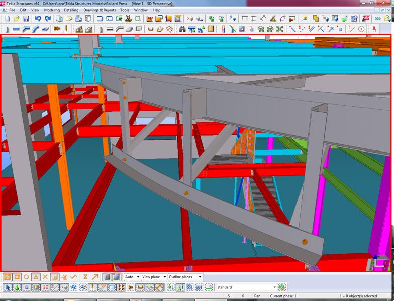
Figure 1
With building information modeling (BIM), a change made
to the model automatically updates the drawings, the bill of
material, and CNC data.
Fabricators have been reaping the benefits of building information modeling for decades. While it wasn’t called BIM 20 years ago, it was still an early form of what we know as BIM today.
But what is BIM? In its most simplistic form, it’s a 3-D model with information associated with the objects contained in it. In its most complex form, it is a multidiscipline, 5-D (X, Y, Z, time, and money) model shared in real time with all project participants. Beyond that, people often disagree on what constitutes BIM.
Some might argue BIM is BIM only when it is shared. I would suggest that BIM is BIM even when the model is used by a company strictly for in-house use. This so-called “lonely BIM” has as much validity as BIM shared with other project team members. In fact, this enhanced workflow use of BIM, or model sharing, has only become more widespread over the past five years or so.
The plant and process industry adopted the earliest 3-D modeling applications to better visualize complex layouts like piping system runs. Product designers and manufacturers also began using 3-D models to visualize and communicate product designs, while architects built physical 3-D models to help clients understand their designs. And while none of these early models contained the level of detail found in today’s BIMs, they did provide a basic means to visualize, communicate, collaborate, and identify potential problems during the design and planning stages.
The use and capabilities of 3-D models evolved rapidly throughout the 1990s and into the 2000s as the cost of the technology became more affordable and desktop computers grew faster and more capable. When 3-D models began to include information that could be used to drive fabrication machines in the shop and produce automated drawings and reports, they evolved into the more common form of BIM we know today.
Some structural steel fabricators were quick to realize these early benefits of BIM. For more than a decade, fabricators have created highly detailed and intelligent 3-D models to produce shop drawings, generate reports such as bills of material (BOMs), and extract CNC data to drive machines in the shop, aiming to eliminate common errors.
Contrast this to the conventional way of fabricating structural steel: The fabricator receives the structural engineer’s design drawings and has steel detailers produce 2-D shop and erection drawings without any interdependency. Pieces are manually tabulated from the engineering drawings to create an advance BOM, also disassociated from the shop and erection drawings. Assemblies are then manually fabricated in the shop piece by piece. If CNC machines are available, they have to be manually programmed from information on the shop drawings. Each of these steps opens the door to oversights, miscalculations, and inconsistencies that often lead to serious and costly errors.
The introduction of BIM software resulted in measurable efficiencies for steel fabricators. Instead of the fabricator having to update the project by adding information to the drawing, any model changes automatically update the drawings, the BOM, and CNC data. This reduces errors caused by having to manually update several documents and databases every time a change is made (see Figures 1-3).
Recognizing the value of exchanging the information contained in structural steel models, the American Institute of Steel Construction (AISC) adopted the CIS/2 file format, building on the Steel Detailing Neutral File (SDNF) format already being utilized in the construction industry. Adopting this neutral file format marked the beginning of model sharing and interoperability between the models produced by structural engineers for their own analysis and steel fabricators. These “seed” models allow the steel fabricator to quickly generate advance BOMs and order the steel much earlier in the project. Having the steel on hand and ready to fabricate as soon as shop drawings are approved cuts valuable time out of the schedule.
Despite the time and accuracy benefits of model sharing, it is still a work-in-progress for the architecture, engineering, and construction (AEC) industry for a couple of reasons. First, it relies on other project partners getting onboard. Second, there are some contractual issues that must be resolved between the parties sharing the model.
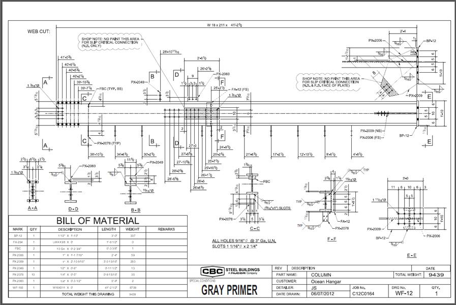
Figure 2
BIM reduces errors caused by having to manually update
documents, such as this drawing and BOM, every time a
change is made.
Traditionally, the drawings the structural engineer produces are the contract documents. Whatever is represented on those drawings is what the fabricator is responsible for producing. For model sharing to achieve the maximum efficiency and accuracy benefits for the project, there must be an agreement between the structural engineer and the structural steel fabricator that accounts for the model in the contract documents.
Some of the more advanced construction teams are using model-based project delivery methods such as integrated project delivery, or IPD. This is a contractual agreement between all construction team members in which contractual models are used and project risk is shared. Model sharing drives down waste and project costs and reduces the schedule through project information accuracy. Most in the construction industry agree that IPD is where the construction industry is headed, but it’s not widespread yet.
When fabricators make the best use of engineering models, they can save time and reduce errors. But if the engineers are not willing to stand behind their models, using those models to order steel or as the basis for the detailing model, for example, puts the fabricator at risk. It falls on the fabricator and steel detailer to assess the risk of relying on an engineering model that is not defined as the contract document. If the fabricator knows and trusts the engineering firm and assesses their model building discipline as high, the benefits may be well worth the risk. That liability and risk, however, are the “grit in the machine” that keeps true model sharing from being widely adopted.
When models are being shared, structural steel fabricators have an opportunity to add even more value to the project by combining the mechanical, electrical, plumbing, fire protection, and other models with the structural steel model. Building the project virtually makes it easy to identify clashes and find design mistakes and oversights. These problems can be corrected in the model, which is a huge benefit over discovering them on the job site, where correction is always costly in terms of time, money, and waste (see Figure 4).
IPD can improve project delivery and provide the owner with a much more cost-effective project. However, despite its proven benefits, the fear of shared liability is slowing IPD’s adoption and causing many in the construction industry to cling to traditional project delivery methods.
Another benefit of using BIM for structural steel fabricators is the integration between the model and steel management system (SMS) software packages, such as FabTrol, FabSuite, StruM.I.S., and Steel Projects, for material and cost management.
Without this integration, the fabricator has to manually add in potentially tens of thousands of parts specified on the shop drawings into the SMS program. With BIM, the information and associated drawings can be imported directly to the program. Updating the information is just as simple.
While fabricators have been using BIM for several years to reduce errors and improve project efficiency, a new role for BIM is emerging. SMS programs now organize and simulate work on the shop floor to resolve bottlenecks, allowing the fabricator to optimize the schedule before fabrication begins. There are now a half dozen structural steel fabrication shops in the U.S. that are nearly fully automated. They plan, schedule, and run simulations of their work processes based on information coming out of a building information model before work begins on the shop floor.
Project management tools allow fabricators to schedule, record (via bar code or RFID), and visualize a project’s progress, such as which assemblies are on the shop floor and which are already on their way to the job site. While full project and shop floor automation is cutting-edge, this technology can be implemented in stages to improve project management and shop floor efficiency.
The core needs of fabricators haven’t changed much over the years. To maximize profit, they need to be able to efficiently and cost-effectively fabricate and deliver steel assemblies that can be erected on-site with no fit-up problems. To do that, they have to have quality, detailed information from which to fabricate.
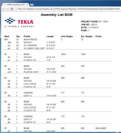
Figure 3
BIM allows the steel fabricator to generate advance BOMs
and order the steel much earlier in the project.
As the use of BIM evolves in the structural steel fabrication industry, the need for shop floor drawings will decrease as shops become more CNC-based and as the adoption of robotic welding and fitting automates more work processes. Instead of having people running the fabrication machines on the shop floor, fabricators will rely more on an automated data feed from BIM. Moreover, as people begin to trust the data coming from the model, they will become less dependent on shop drawings. Some fabricators have already eliminated paper drawings from the shop floor. Instead, they rely on CNC data completely or reference digital drawings saved in the PDF format on tablet computers as necessary.
Once the general AEC industry joined the structural steel fabrication industry on the BIM bandwagon, BIM was driven into other facets of the building industry. Recognizing that structural steel needs to engage digitally with other materials and trades in BIM work flows, the AISC began adopting the Industry Foundation Classes (IFC) file format instead of CIS/2 and is now coordinating its evolution with software providers to include all fabrication-level information—not just coordination-level information—allowing the steel fabricator’s model to become a meaningful part of the entire project team work flow while maintaining the detailed information required specifically for fabrication.
IFC has become the industry-standard neutral file format for exchanging BIMs among all construction disciplines from structural steel to concrete, mechanical, electrical, plumbing, fire protection, and more. Without IFC, even the relatively slow adoption of model sharing in the construction industry would not have happened as quickly as it has.
Beyond sharing model information among project team members in the office, BIM also is making its way onto the job site to ensure components are placed correctly. Consider anchor bolts, which all too often are cast into concrete in the wrong position. To solve this common problem, anchor bolt locations can be extracted from the BIM file and fed into a robotic total station survey system that can mark exactly where the bolts need to be placed on the building site. This can save days of removing anchor rods or sending components back to the shop to be adjusted.
Alternatively, the robotic total station can be used to capture the precise location of installed anchor bolts prior to mobilization of the steel erector. The engineer and steel fabricator can assess and resolve any potential misalignments in the 3-D model environment so that adjustments can be made to the steel components in the shop before they are shipped to the job site.
Steel erectors can also use model information for planning and tracking in the field. The location of steel assemblies on the job site, installation plan, and erection progress can be visually communicated to the owner, project team, and erection crew in an easily understandable fashion. In all three examples, these job site efficiencies are possible only with BIM.
In the not-too-distant future, BIM will rule and govern the construction process, start to finish. It will become the contract documents in a project, and this practice will streamline the work flow and reduce errors and waste to the benefit of all stakeholders. Instead of each subcontractor creating its own model, each trade will add to a central, federated, cloud-based BIM, producing a comprehensive information repository and coordinated environment for the entire project.
What’s more, fabricators will move into a model-based, lean production environment where information coming straight from BIM drives all fabrication machines, including robots, and eliminates the dependency on paper drawings and manual fitting and welding. In the field, BIM will solve the problem of misplaced building components and costly corrections. All of this is happening now, but we’re in the early stages of proving how BIM enables an efficient and accurate work flow—not only in the office, but in a full office-to-shop-to-field work flow.
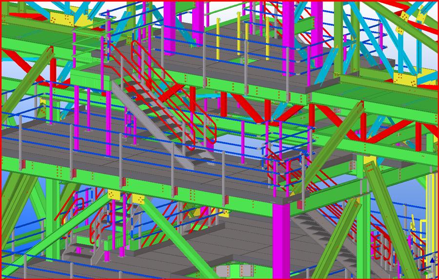
Figure 4
Building the project virtually makes it easy to identify clashes
and find design mistakes and oversights, which can be
corrected in the model.


The Fabricator is North America's leading magazine for the metal forming and fabricating industry. The magazine delivers the news, technical articles, and case histories that enable fabricators to do their jobs more efficiently. The Fabricator has served the industry since 1970.
start your free subscription
Easily access valuable industry resources now with full access to the digital edition of The Fabricator.

Easily access valuable industry resources now with full access to the digital edition of The Welder.

Easily access valuable industry resources now with full access to the digital edition of The Tube and Pipe Journal.

Easily access valuable industry resources now with full access to the digital edition of The Fabricator en Español.
In this episode of The Fabricator Podcast, Caleb Chamberlain, co-founder and CEO of OSH Cut, discusses his company’s...


