


Senior Software Engineer
Cutting with a “soft tool”—be it a laser beam, plasma arc, oxyfuel flame, or waterjet—has in many ways become a defining technology of modern sheet metal and plate fabrication. No cutting method is perfect in every way, of course. Each comes with advantages and disadvantages.
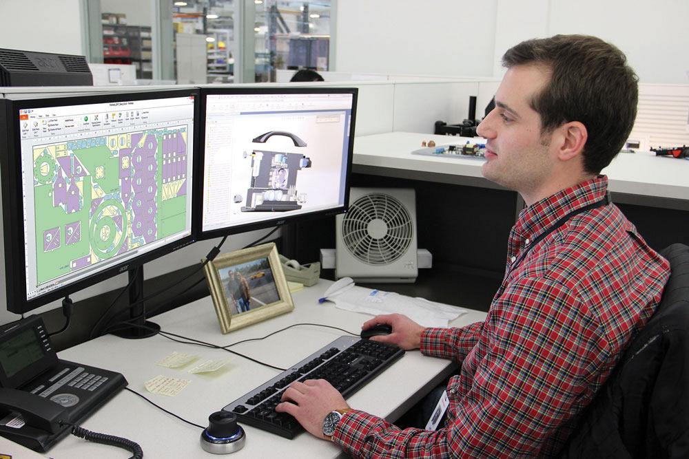
Thankfully, fabricators can mitigate the weaknesses and accentuate the strengths, and one way to do it is to develop a smart strategy around something that’s at the heart of every cutting process in this business: nesting.
Laser cutting excels at producing precision parts in sheet metal and thin plate. Consider a typical application: a high-volume job cutting rectangular appliance panels of different sizes from 1/8-in.-thick stainless steel coated with a laser film. Appliance panels require high-quality fit and finish.
Vaporize. Because this stainless material has a protective film, a nest will need to incorporate the vaporize function to maintain cut quality. This programs the laser to trace the profiles at a lower wattage before actual cutting, burning away the film.
Slug Destroy. A laser cutting nesting strategy also must keep the process as stable as possible. As the laser cuts small interior profiles, it can leave behind cutouts, or slugs, that can tip up and create a collision hazard for the cutting head. The slug destroy strategy eliminates this risk by slicing the cutouts into small pieces during cutting so that they fall through the slats of the table.
Grain Restraint. Since appearance is important for this appliance panel application, the laser must cut parts so that the material grain is in a consistent direction. To maintain a uniform appearance of material grain on the panels, a programmer must nest parts only in orientations that run parallel to the material grain, which can be done by using a grain restraint strategy, which sets a restriction on the rotation of the parts before nesting.
When nesting automatically, the software will nest these parts at only the allowed orientations. If the programmer nests manually, the software will signal an error when a grain restraint is violated. This prevents parts from being cut incorrectly and needing to be recut, a waste of both time and material.
Common-line Cutting. Again, stainless is expensive, so material utilization is important. This is where another nesting strategy can help. Common-line cutting (CLC) is a technique in which a single cut is used to cut the edges of two adjacent parts at the same time. This shortens cut length and processing time and better utilizes material, since parts are nested closer to each other.
A nest layout can employ various CLC strategies. It could have two identical parts with a common cut line (pair CLC) or four identical parts (quad CLC) sharing cut lines, such as a square divided into four parts. These pair or quad CLCs can then be arranged in a nest layout like any other part. A nesting layout also can have part edges aligned with edges of the plate (plate edge CLC), so that those part edges don’t require cutting.
When nesting automatically, the software can combine a CLC part group with different parts that are already nested. For instance, a quad CLC group (again, four identical parts that share common cut lines) also can share a common cut line with a separate piece in the nest. This is called advanced CLC nesting.
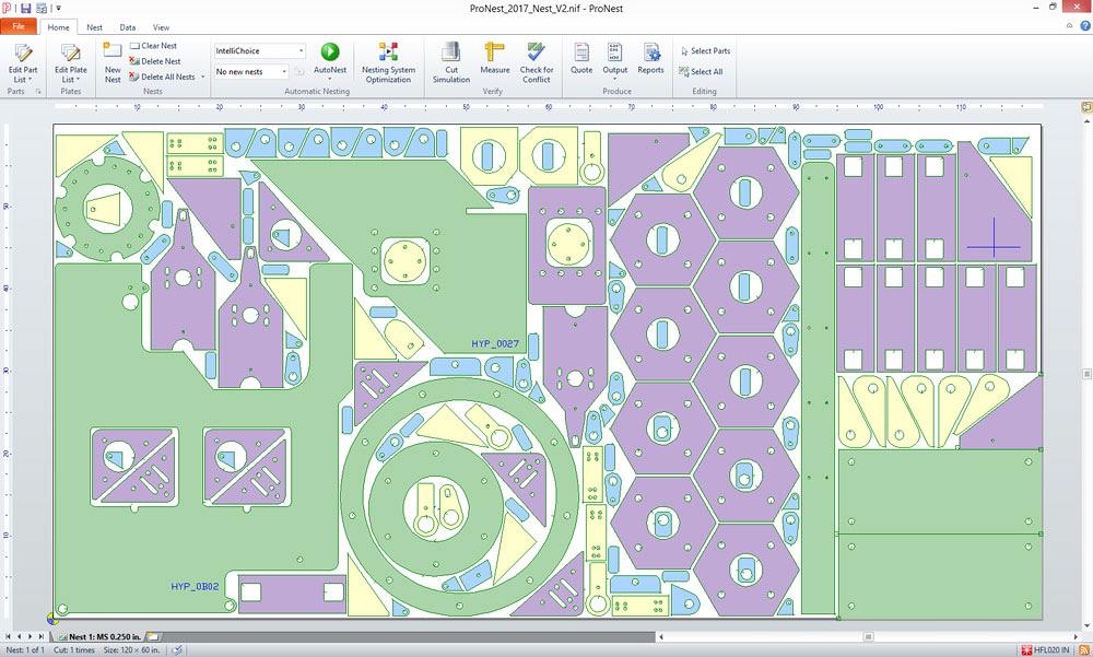
For maximum material utilization, parts are nested within the cutouts of other parts.
A programmer also can employ a multipart CLC strategy by creating and editing CLC parts when nesting manually. He does this using two strategies, the first being a CLC array. This method arranges a number of copies of a part into a grid, such that all adjacent parts are cut using common lines. This approach works well for large quantities of small to medium-sized parts. The CLC array allows all parts in a nest layout to be common-line cut, which reduces space between parts dramatically and yields significant material savings.
Programmers also use a dynamic align nesting strategy, which arranges different sized rectangular parts into a grid that is common-line cut. It differs from CLC array in that it produces a grid that contains different parts instead of multiple copies of a single part. Parts in each column are arranged such that their edges are all aligned to one side. Dynamic align uses an advanced rectangular nesting algorithm that generates many different possible results, chooses the best one, and optimizes the cutting path.
Optimization Strategies. Some nesting approaches try different combinations of part placements, looking ahead a certain number of steps as each part is placed and then backtracking to try other possibilities, all in an effort to find the best result. Rectangular optimization is one such approach. Used for medium to large, mostly rectangular parts, the nesting strategy can improve material utilization significantly.
Another way to improve material utilization is to try different automatic nesting strategies—on different sheet or plate sizes if multiple sizes are available—and then choose the best result. Nesting system optimization automates this process and provides a good way to produce nests with better material utilization. Although it takes a little more time for a PC to generate nests for every combination of plate size and nesting strategy, the improved material utilization often makes this strategy worthwhile.Consider a plasma application involving the cutting of bolt hole flanges on 0.5-in.-thick mild steel, producing a large quantity of a single part. The programmer must deal with several major concerns, including material utilization, lead placement (both lead-ins and lead-outs), and hole quality.
Hole Cutting Optimization. To improve hole quality, plasma system makers have developed techniques that control the attributes of the plasma arc to ensure a hole is as circular, taper-free, and burr-free as possible.
Pattern Array. To nest this application—again, involving high quantities of identical bolt hole flanges—several nesting strategies could help the programmer produce excellent results, one being pattern array. Using knowledge of the part shape, the strategy generates a regular pattern from a large quantity of the same part, often trying different pairings of the part to produce a result that achieves the best material utilization. Pattern array also chooses a lead placement that minimizes the space between adjacent parts. Circular parts, such as bolt hole flanges, are excellent candidates for pattern array.
Collision Avoidance. After cutting bolt holes, the torch could collide with tipped-up cutouts as it moves to cut the remaining profiles. A strategy called collision avoidance uses a combination of profile sequencing, lead repositioning, full and partial torch raises, and avoidance paths to eliminate the risk of torch collisions.
For cutting carbon steel that’s 2 in. thick or more, oxyfuel cutting often can produce a good result, though the process comes with some challenges, including slow pierce and cut times, heat management, and large heat-affected zones.
Consider a large run of rectangular counterweights cut out of 2-in.-thick carbon steel. The goals of nesting are to minimize production time while maintaining good part quality and material utilization. Several nesting strategies can help.
Multitorch Cutting. Many oxyfuel setups use multiple torches that cut parts simultaneously and, hence, greatly reduce cutting time. A nesting strategy that supports multiple torches can create an efficient nest layout that uses all available cutting heads.
Pair CLC. Oxyfuel also can take advantage of CLC, especially pair CLC. Two copies of a part can be cut together so that they share a common line. This not only reduces the space required for the parts on the nest, but also reduces the number of pierces required to cut the parts, shortening production time. For oxyfuel cutting, in order to maintain heat, the CLC pair function uses a cut path that does not cut over a previously cut kerf width.
Chain Cutting. Oxyfuel also can make use of chain cutting, in which the lead-out of one part is connected to the lead-in of another. The torch remains on between parts, reducing the overall number of pierces. Any number of parts can be chained together, though heat buildup and plate integrity must be managed.
Heat Dissipation and Cut Sequencing. Heat buildup can cause the plate to expand and move, which can affect part quality and accuracy. A programmer can mitigate this by using a heat dissipation cut sequence, which distributes heat evenly across the plate by cutting parts located in different regions of the plate. Unlike most cut sequencing methods, this approach does not seek to minimize the distance the torch moves between parts. Rather, it attempts to prevent heat buildup in any area of the plate to reduce plate movement and preserve part quality.
Lock Leads. Lock-lead styles can help maintain plate integrity and reduce plate movement as parts are cut from the nest. The shape of the lead creates an interlocking effect on the remaining plate, which limits part and plate movement.
Automatic Move Leads. When nesting automatically, the software positions leads to ensure that, after cutting, the part is freed where more material exists, instead of along a plate edge. This helps maintain plate integrity and preserve part quality and accuracy.
Consider waterjet cutting of cosmetically critical thick plate used for an art project. The material is expensive and the cutting speed is slow, so minimizing the total cut length is important, as is maintaining the ability to reuse scrap.
Grain Restraint and CLC. Grain restraint can ensure all parts will have grain running in the correct direction. Using multiple-part CLC can shorten total cut length and, hence, overall production time. And because this is waterjet, with no concerns over heat buildup, any number of parts can be common-line cut together. Automatic nesting strategies are useful in this case, but having a way to modify (or produce) the results manually is equally important.
Plate edge CLC strategies on waterjet also can prove useful. If the material contains finished edges, as it would on a remnant, the edges of nested parts may be aligned with them so that one or more edges of the part need not be cut at all.
Viewing the Nest Image. This is an art project, so surface quality is everything. Occasionally, the material may contain imperfections, or aesthetic defects in the grain, requiring parts to be placed elsewhere. This can be handled by superimposing an image (picture) of the material over the nest, in the software nesting window, so that parts may be moved to locations where the material is visually appealing.
Remnant Tracking. Because material for this art project is expensive, remnant tracking really can pay off. Today’s nesting systems can help shops track remnants, storing them for later use.
Certain strategies are more common with certain cutting methods; for instance, the locking lead-in technique is most prevalent when cutting thick plate with an oxyfuel flame. But some strategies aren’t limited to a specific cutting technology. Strategies like remnant tracking and grain restraint, for instance, can work for any cutting process.
That said, every primary cutting process in metal fabrication can produce the desired result when approached intelligently using advanced nesting software. Having access to the most appropriate nesting strategies and productivity tools for each process will help achieve the best outcome.
Mark Schuessler is senior software engineer at Hypertherm Inc., 21 Great Hollow Road , Hanover, NH 03755, 603-643-3441, www.hypertherm.com. Photos courtesy of Hypertherm Inc.

The Fabricator is North America's leading magazine for the metal forming and fabricating industry. The magazine delivers the news, technical articles, and case histories that enable fabricators to do their jobs more efficiently. The Fabricator has served the industry since 1970.
start your free subscription
Easily access valuable industry resources now with full access to the digital edition of The Fabricator.

Easily access valuable industry resources now with full access to the digital edition of The Welder.

Easily access valuable industry resources now with full access to the digital edition of The Tube and Pipe Journal.

Easily access valuable industry resources now with full access to the digital edition of The Fabricator en Español.
In this episode of The Fabricator Podcast, Caleb Chamberlain, co-founder and CEO of OSH Cut, discusses his company’s...


