


Senior Editor
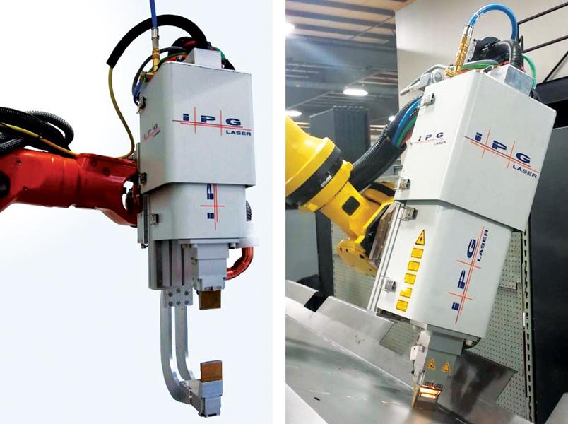
Like a resistance welding head, this fiber laser welding head clamps material from above and below, as shown on the left. On the right, a single-side-access system applies pressure from above.
Laser welding has its long-known merits, particularly for its high quality, repeatability, and low heat input. It also opens up options when it comes to weld joint geometry. A laser really does expand the welding engineer’s creative palette.
Of course, this happens only if engineers overcome some challenges. The most well-known is maintaining a tight gap between the base metals. Engineers also need control over the welding environment, including fume and spatter, and they must address safety concerns, especially when working with fiber and other lasers with 1-micron-wavelength beams. Engineers have overcome these problems in various ways, and these solutions are a big reason that laser welding has really started to take off in recent years.
One way to overcome these issues takes a unique approach. IPG Photonics’ Laser Seam Stepper doesn’t rely on complicated workpiece fixturing but instead, like resistance spot welding, incorporates material clamping in the welding head itself. Once aligned, the head creates a light-tight seal between itself and the workpiece, effectively creating a small Class 1 enclosure, which eliminates the need for a large enclosure around the entire workcell.
The optics can direct the beam in a weave, which can be changed to meet strength and other application requirements. The bead can be customized to various “frequencies,” including those so high (that is, a dense weave) that the resulting joint looks as if it’s simply a wide weld bead—though because of the weave geometry, it’s far stronger.
The technology’s development goes back to 2010, when the first prototype passed long-term tests at Volkswagen. The German automaker needed a way to weld its lightweight, high-strength material. In other words, it needed to apply a strong weld without excessive heat—a classic application for laser welding. Of course, the company was replacing resistance spot welding, which still had one big advantage.
“When you do resistance spot welding, you always clamp the workpiece as part of the process,” said Michael Wiener, senior applications engineer at IPG’s offices in Novi, Mich. “Fixturing is key for a good laser weld. So we wanted to design a tool that combined these two advantages—the clamping along with the low heat input, high process speeds, and high repeatability of the laser weld.”
The unit’s clamping mechanism floats much like a conventional spot welding head. If a component, be it a car part or anything else, is slightly higher or lower than expected, the head’s compensation unit allows it to realign to the new part position as it clamps down with up to 3,000 N of force.
Inside the head is a conventional welding optic mounted on a servomotor, which can move the laser up to 40 mm lengthwise. The unit is mounted on a pivot point that basically “wobbles” the weld optic to create the weave, with a frequency between 0 (a straight line, no weave) and 25 Hz (a weave that’s so tightly packed, it looks like one weld). The weave increases the weld interface area, which in turn increases the weld strength.
“Every application is different,” Wiener said. “Some need very low heat input and a very fast weld, so they have no weave at all. Then we have applications where we weld 3- or 4-mm-thick material, where we take advantage of the full weave to create a wide weld that has a large weld interface and more strength.”
Between the weld optic and the workpiece surface, a suction unit sucks out fumes and spatter. In applications requiring shielding gas—such as when welding aluminum or stainless steel—argon, nitrogen, or other shielding can be fed to the workpiece surface.
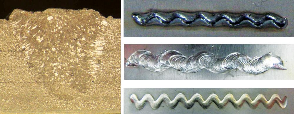
Different weave geometries create welds with different strength and heat input characteristics.
The system has been used on galvanized and other coated material, and here engineers use the same techniques to overcome the zinc outgassing issues that occur with any laser welding system. They sometimes purposely create a controlled gap through dimpling or other methods. Or sometimes they remove the galvanized coating in the weld area.
Like other fiber laser heads, the optics have a replaceable cover-slide module on the bottom. In addition, a circular nozzle near the slide can feed either shielding gas or compressed air to prevent spatter and fume from hitting the cover-slide glass. Earlier prototypes had used a cross-air knife perpendicular to the workpiece, but as Wiener explained, “the circular nozzle has a much lower flow but it’s more effective than a cross-air knife.”
The technology has also been adapted for single-sided-access applications, particularly those in heavy industry: agriculture equipment, railcar manufacturing, even shipbuilding. In these applications, the head can apply up to 1,000 N of force from above, though of course the workpiece needs to be supported from the back side.
Many of these applications previously used massive resistance spot welding electrodes, which needed to access the base materials from both sides. Other applications, including those in shipbuilding, used gas metal arc welding (GMAW), which caused distortion problems. With lasers, Wiener said, “you can tightly control the heat input and level of penetration.”
These applications, one involving 4-mm-thick aluminum, use a high-frequency weave, producing weld joints with a lot of weld interface area. Because the laser focuses the heat and produces the weave extremely quickly, heat input remains relatively low, which eliminates the distortion problem.
Wiener added that the weave geometry has been critical to the technology’s success, and it goes back to the area of weld interface, or the area of contact of fused metal. A conventional laser weld (depending on the beam characteristics and the material being welded) has a weld interface area of approximately 0.5 mm, which often isn’t sufficient to withstand harsh tensile tests. But set the weave frequency ±1 mm, and you effectively add 2 mm of weld interface.
“So now, instead of having 0.5 mm of weld interface, you now have 2.5 mm of weld interface,” Wiener said. “That is a huge performance increase, especially for thicker materials. The weave doesn’t take any additional cycle time, but it adds strength to the weld.”
The system has a maximum laser power of 4 kW and works with lap joints, but not butt, groove, or other joint geometries, so it’s not a solution for every application. But the fact that the system does create an enclosed space for the laser weld, and clamps the material before welding, has opened up a new area: manual laser welding. Mounted on a manipulator, the laser head can be moved and positioned by the operator. “They move it to each individual weld location,” Wiener said. “They then implement the laser weld.”
He added that the manual system has been used for repair work and for welding large parts, such as a railcar application for which it was impractical to develop a program and automate the process, because the part tolerances were somewhat wide.
This laser welding technology is another tool in the welding engineer’s toolbox. It’s fast, and yet not as fast as certain remote laser welding setups, where the laser beam jumps from one joint to the next nearly instantaneously. Of course, remote laser beam welding also requires significant and often costly fixturing.
“This is where you do your evaluation in the beginning [of the project],” Wiener said. “What is most important for you? Is it really fast laser cycle time? Or do you want to simplify fixturing and eliminate the laser enclosure?”
Images courtesy of IPG Photonics—Midwest Operations, 46695 Magellan Drive, Novi, MI 48377, 248-863-5001, www.ipgphotonics.com.


The Fabricator is North America's leading magazine for the metal forming and fabricating industry. The magazine delivers the news, technical articles, and case histories that enable fabricators to do their jobs more efficiently. The Fabricator has served the industry since 1970.
start your free subscription
Easily access valuable industry resources now with full access to the digital edition of The Fabricator.

Easily access valuable industry resources now with full access to the digital edition of The Welder.

Easily access valuable industry resources now with full access to the digital edition of The Tube and Pipe Journal.

Easily access valuable industry resources now with full access to the digital edition of The Fabricator en Español.
In this episode of The Fabricator Podcast, Caleb Chamberlain, co-founder and CEO of OSH Cut, discusses his company’s...


