


Know your press brake safeguarding options
Properly trained, users should know what safeguards can and cannot do
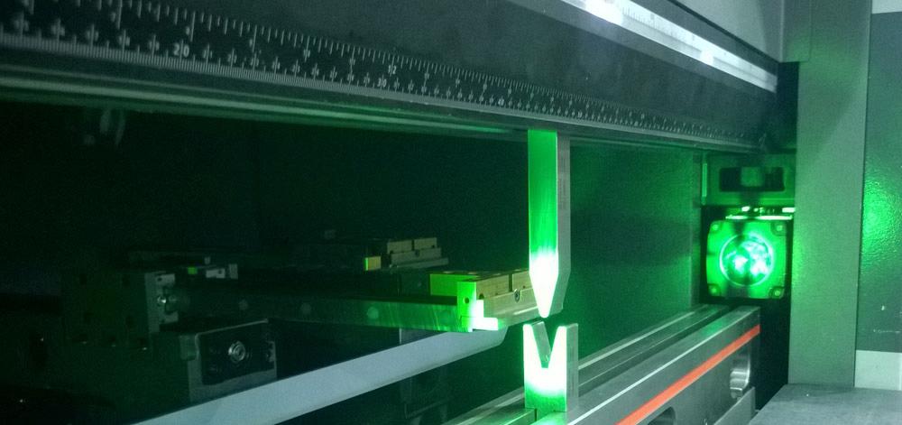
A vision-based safety system on a press brake scans the area just below the punch tip.
Editor’s Note: The following article is based on material from the Press Brake Safeguarding Certificate Course, a one-day event organized by the Fabricators & Manufacturers Association International® and conducted by Doug Raff, vice president and principal of Tustin, Calif.-based Paragon Industrial Controls, 714-564-9925, www.paragon-ind.com. For more on FMA’s certification and certificate courses, visit www.fmanet.org/certification, or call 888-394-4362.
Imagine a press brake operator bending one long, narrow part after another. The press brake has appropriate safeguarding. It has an interlocked barrier in the back to ensure no one can step behind the machine with the automatic backgauge in motion. It has hard guards on either side of the workspace. And it has a laser-based safety system that rides along with the ram, emitting a laser just under the punch to ensure no unexpected obstruction, like a body part, is in the way. While making the second bend on the narrow channel, the operator pushes the foot pedal to commence the bending cycle and the part crushes the very tip of his thumb up against the upper tool.
How could this have happened?
When it comes to safety in manufacturing, there’s much talk about “designing out” the hazards. If that’s not possible, you eliminate or at least minimize the hazard by using appropriate safeguards—all well and good.
In certain circumstances, however, completely eliminating the hazard just isn’t possible. And even if it were possible, no operator should approach a machine that exerts tons of forming pressure without the right training and safety information.
There’s a good reason U.S. government regulations require a job hazard analysis. Ideally, operators should know what the safeguards on the machine are and are not capable of, and how to operate the machine safely, with extremities as far away from pinch points as practical.
The operator in the previous example should have known that a laser-based sensor riding on the ram is muted (that is, becomes ineffective) when the ram reaches 0.25 inch from the lower die. On many machines, that’s when the ram changes from its approach speed to its much slower bending speed. It’s also a time when an operator holding a narrow part might get the very tip of his thumb caught between the part and the tooling.
This illustrates why good safety training is so important. Operators without such training—like about how to hold a narrow part properly, away from the pinch point with his fingers and thumbs beneath the part—can still get hurt operating a properly safeguarded press brake, even with all the latest bells and whistles and most effective safeguarding devices. At most fabricators, no other machine in the shop requires an operator to have his fingers so close to so many tons of force.
OSHA regulations require that an employer have written documentation proving that the company has conducted a workplace hazard analysis. The details are in OSHA 1910.132, the section of the regulation devoted to personal protective equipment.
OSHA gives broad guidelines. To identify the hazard, you need to identify the worker, his or her task, the tools used, the work environment, and the steps taken to perform a job. What can go wrong? What are the consequences? How likely is it that a hazard will occur?

Figure 1
A risk assessment identifies foreseeable hazards as well as the probability and severity of the harm.
For more specifics, fabricators can turn to the ANSI B11.3-2012, Safety Requirements for Power Press Brakes, a standard used by OSHA as a reference in citations, and ANSI B11.0, Safety of Machinery: General Requirements and Risk Assessment.
These standards outline a risk assessment process that identifies foreseeable hazards as well as the probability and severity of the harm (see Figure 1.) With the risk assessment in place, the shop goes through the hazard control hierarchy. Can the unsafe act be designed out of the process, substituted by another process, or eliminated altogether?
If not, can guards and safeguarding devices be used (so-called “engineering controls”) to eliminate the potential of injury?
Then comes training. Safeguards themselves use mechanical, pneumatic, or electrical systems to function, and there’s always a chance—albeit sometimes a minute one—that these systems will fail. Moreover, these safeguards are designed and installed by people, and nobody’s perfect.
The press brake itself has to meet certain standards, as spelled out in B11.3. For instance, all press brakes also need to have control reliability. This includes a machine control that has redundant circuits and a way to monitor that such redundancy is maintained.
The bottom line is that an operator needs to know how to operate the equipment safely, like knowing how to support a workpiece correctly. Part of this is knowing how exactly safeguards work and what they can and cannot do when it comes to employee protection.
Safeguarding With Caveats
When it comes to safeguarding, the safety standard lists plenty of options. Some aren’t really in common use, but the B11.3 standard mentions them, mainly to ensure it covers a broad range of application possibilities (see Figure 2).
For instance, the standard says that if the bending application opens only to 0.25 in. or less, then that’s considered too small of an opening to create a pinch point in most (though as discussed previously, not all) circumstances, so no other safeguard is needed in front of the workspace. Of course, most press brake applications require an open height higher than that, so this “safeguarding method” really isn’t practical in real-world applications.
The standard also states that maintaining a safe distance (between 4 in. and 10 in., depending on the application) can qualify as a safeguarding method, but only if the application has no other safeguarding alternative, be it a physical barrier or an optoelectronic device. That application also needs to be either a one-time part or a small-quantity run that lasts no more than four hours per month. The standard mentions even more limitations, but the bottom line is this: Safe operating distance is a safeguarding method of last resort. Besides, with today’s safeguarding technology, few applications qualify.
The safeguarding standards also account for the use of a safe speed, in which the ram moves at a slow speed. But OSHA does not recognize “safe speed” as a safeguarding method on its own. Instead, it must be used in conjunction with a machine’s primary safeguarding device.
For instance, if a part obstructs the view of an optoelectronic safeguard (such as a light curtain or laser- or camera-based system) when the ram is open beyond the 0.25 in., the safeguard may need to be muted. In these cases, slowing the speed of the ram can be used as the safeguarding method.
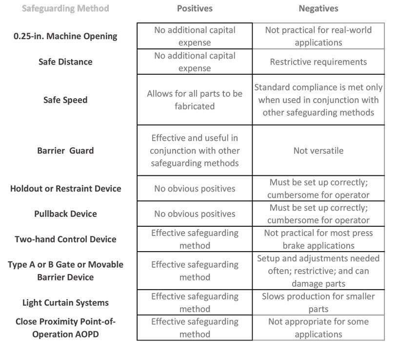
Figure 2
This is a subjective analysis of the safeguarding methods mentioned in the ANSI B11.3-2012 standard. Common arrangements include barrier guards around the back and side of the brake, as well as light curtains or laser- or camera-based point-of-operation devices across the press brake bed.
The standard also mentions movable barriers in front of the workspace. This old technology, when set up correctly, can be an effective safeguarding device.
Still, if they are used, they’ll need to be adjusted often, they can restrict operator movement, and they make it easy to damage parts. So usually they’re not ideal.
Two-handed control devices are in the standard too. To actuate the machine, the operator must press both buttons at once. These are far more common on hand-fed stamping presses, but they occasionally have a place in other press brake work. For instance, if a press brake operator is performing just one bend, or using special tooling to perform a combination of bends in one hit, a two-button controls safeguard might suit. This works only if the part blank can be placed steadily in the work area, perhaps with the help of a magnetic backgauge, so the operator doesn’t need to hold the blank when the ram is in motion. That’s a narrow range of applications, to be sure, but the safety standard takes them into account.
Decades ago, it represented good safety practice to require a brake operator to use a pullback device, such as those that wrapped around the hands in a certain way, or other physical restraint.
These systems literally pull back the operator’s hands away from the pinch point during every stroke, though they give the operator freedom of movement to load and unload parts. They do need to be adjusted for the individual, though, to accommodate a person’s height, hands, and arm length.
Such physical systems may make sense if you just have no other alternative. For instance, they may be a choice for an old press brake where it may be cost-prohibitive to upgrade that machine with a new control that modern safeguards require. However, it is difficult to monitor these devices, and they typically are set up incorrectly.
Having a person operate an old brake with a physical pullback is better than no safeguard at all. Does using a physical pullback or restraint on certain press brakes comply with safety standards and regulations? It can, with correct use and proper training. Is it ideal? In most cases, not really.
Common Safeguarding Methods
The most common safeguarding usually involves a combination of hard guarding and optoelectronic sensing devices. A press brake must have some type of guarding behind the machine to prevent anyone from entering the area during operation. An automatic backgauge looks innocent enough, but it moves with serious force and can cause serious bodily harm.
Guarding behind the brake could be an optoelectronic proximity guard; if anyone steps through it, the machine shuts down immediately. Alternatively, the machine could have a traditional barrier guard interlocked with the machine control. If anyone opens it during operation, power is cut off from the system and the machine should stop immediately. Alternatively, a machine simply could be placed against a wall in the plant. A press brake also should have barrier guards on each side of the workspace to prevent access. A company’s job hazard analysis and risk assessment determines the best safeguarding method for each circumstance.
The most complex safeguarding occurs at the front of the brake. Fabricators usually choose one of two options. The first is a light curtain, which emits sensing beams in front of the workspace. The second is a laser- or camera-based system that senses objects just below the punch; the safety standard refers to these as close-proximity point-of-operation AOPDs (active optoelectronic protective devices).
Light curtains mount on each side of the press brake bed and emit infrared beams in front of the work area. They can be programmed to be blanked to account for obstructions while the ram is open more than 0. 25 in. And they mute when the punch tip reaches the workpiece (at an opening of 0.25 in.) to commence bending.
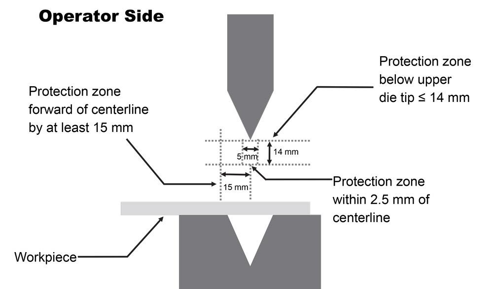
Figure 3
Close-proximity guarding must have a protection zone below the punch (upper die) tip equal to or less than 14 mm, as
well as 2.5 mm in front of and behind the punch tip.
The nature of the light curtain does create a few problems for press brake work. No matter how short the required safety distance is for the press brake at hand (see sidebar), a light curtain needs to be placed in front of the work area. So when an operator needs to bend a small part, he can’t help but penetrate the light curtain when the brake is high in the stroke.
Technically, the operator could wait until the tools are 0.25 in. apart and then slide the small workpiece in between. But what if that workpiece has more than one bend? This frustration can lead to “muting abuse,” with the operator muting the light curtain high in the stroke, just so he can get the job done.
This has been why point-of-operation devices that use lasers or cameras have become very popular in recent years. These close-proximity guards sense the presence of objects just below the punch. When the brake ram stops its approach and starts its bending speed just above the workpiece, the safeguards mute until the return stroke.
According to the most recent B11.3 standard, these devices need to be installed to sense an area within 14 mm (0.55 in.) of the upper punch tip (see Figure 3). These devices also can monitor the stopping speed. According to the standard, if the machine or the safeguarding system doesn’t monitor stopping speed, then a stop test needs to be performed every four hours.
These devices also use a safe speed, described previously. When the safeguard mutes, the brake ram slows to this safe speed—defined as 10 mm/second or less—and that safe speed needs to be monitored continuously. If it detects that the ram is moving more than 10 mm/second, then the machine must stop and create a fault that needs to be cleared by depression of a reset button.
An operator can initiate special modes, like box-bending modes, in which the machine mutes a portion of the sensing area (usually toward the front) to account for certain part geometries, like the high flanges of a deep box. Still, the main protective zone directly under the punch tip (±2.5 mm of the punch tip centerline) needs to be active at all times.
Note that these close-proximity guards don’t work for every situation. For instance, these guards work well when all the punches in a setup are the same height; that is, a single passline height across the press brake bed. If you have dissimilar tools—say, a hemming die set next to a punch and a deep V die, each with different shut heights—the safety system may mute when the punch tip reaches the top of the V die. At that point, the space between the hemming tools may be greater than 0.25 in.
They also may not work if you’re using extremely wide tools. For instance, if you have a 3-in.-wide V die, the pinch point may extend beyond the sensing area of a close-proximity safeguard. In these and other instances, a light curtain may be the best choice.
Put Yourself in the Operator’s Shoes
You’ve guarded the front of the workspace, the sides, and behind the press brake. Now, look down. Aside from the rare dual-palm-button setup, most manual press brake machines have a foot pedal for the operator to initiate the bending cycle. This foot pedal needs to be covered on top to avoid inadvertent operation.
Beyond this, many brakes now use what’s known as a three-position, hold-to-run foot pedal. The first position is the nondepressed position, where the machine is idle. When the operator presses on the pedal, he reaches the second position and initiates the bending cycle. If he stomps on the pedal hard, he reaches the third position, which retracts the ram and stops the machine.
Think back to the operator who hurt his thumb because he held a narrow workpiece incorrectly too close to the pinch point. With a three-position, hold-to-run pedal, he could have stomped down immediately as soon as he felt pain.
This illustrates a broader part of safeguarding: Put yourself in the operator’s shoes. What parts does he process throughout a shift? Are there jobs he needs to perform that promote unsafe acts, like reaching behind the tools to support a part?
Safeguarding is only part of the equation. You also need training and good communication. When you mix all of this together, you build safety into the shop culture—which, of course, is the ultimate goal.
This article is for informational purposes only and is not an official interpretation of standards and regulations. To obtain the complete ANSI B11.3-2012, Safety Requirements for Power Press Brakes standard, visit webstore.ansi.org.
Why stopping distance matters
A press brake is a machine in motion that takes some time to stop. How much time determines the minimum safety distance for any safeguarding device. The B11.3 safety standard describes a formula that looks complex, but at its heart it has a simple concept: An operator’s hand (or any other body part) cannot move faster than the response time of a safety system.
If your hand breaks into a light curtain when it shouldn’t, the press brake should stop well before your hand can reach any hazard. It considers the hand speed of operators and also adds a few safety factors to account for certain variabilities, like for variations in stopping performance and the performance of presence-sensing devices.
Most modern press brakes, including hydraulic, hybrid, and all-electric systems, have extremely short stopping distances, which makes the minimum safety distance for safeguarding extremely short as well. This makes for a safe system capable of using close-proximity safety devices. However, older machines, especially mechanical press brakes, require longer minimum safety distances, which may limit the kind of safeguards that will work. This is where stop-time testing plays a role.
Formulas for calculating safety distance can be found in the OSHA safety regulations and the ANSI B11.1-2012 press brake safety standard.
About the Publication
subscribe now

The Fabricator is North America's leading magazine for the metal forming and fabricating industry. The magazine delivers the news, technical articles, and case histories that enable fabricators to do their jobs more efficiently. The Fabricator has served the industry since 1970.
start your free subscription- Stay connected from anywhere

Easily access valuable industry resources now with full access to the digital edition of The Fabricator.

Easily access valuable industry resources now with full access to the digital edition of The Welder.

Easily access valuable industry resources now with full access to the digital edition of The Tube and Pipe Journal.

Easily access valuable industry resources now with full access to the digital edition of The Fabricator en Español.
- Podcasting

In this episode of The Fabricator Podcast, Caleb Chamberlain, co-founder and CEO of OSH Cut, discusses his company’s...
- Trending Articles
1
How to set a press brake backgauge manually

2
Capturing, recording equipment inspection data for FMEA

3
Tips for creating sheet metal tubes with perforations

4
Are two heads better than one in fiber laser cutting?

5
Hypertherm Associates implements Rapyuta Robotics AMRs in warehouse
