


Contributing Writer
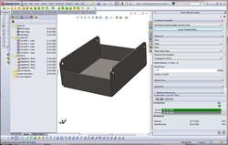
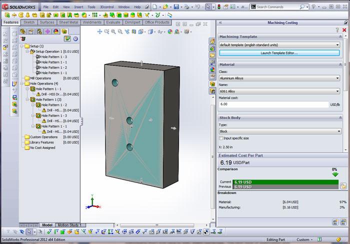
Figure 1: The Sheet Metal Costing tool is shown on the right, the sheet metal model in the center, and the costing details on the left. The system reports four bends in this part.
We open with the usual warning that this article mentions a brand of software by name. The general topic is cost estimating. To that extent, the article may be relevant to fabricators using other CAD systems as well. The information in this article was derived from use and reading the manual; I don’t have any special insight into how or why the tool is the way it is.
The August column demonstrated the use of a couple of analysis tools to refine the design for a bracket. The SimulationExpress analysis tool helped us evaluate the load on the bracket. We used that to adjust the design to meet a target factor of safety. We also observed the relative cost impact of changing the bracket from the original design to meet the required stiffness. The Costing tool built into the SolidWorks® CAD software was a useful indicator of how various features in the model contribute to cost.
This article looks more closely at how you might set up the Costing tool to estimate those costs.
The Costing tool—Figure 1 shows a screen shot—looks primarily at the features in the model to establish a cost benchmark. A secondary input is production quantity. Not to be confused with a full-blown cost estimating system, the Costing tool omits automatic considerations for queuing, schedule, expediting, dedicated tooling, or other expenses that are routine for a professional cost estimator.
The out-of-the-box settings for the Costing tool allow you to discover consequences that are obvious to professional manufacturers: More costs more. More holes, more bends, more material—all mean more cost. It also reveals that the quantity ordered and the manufacturing batch size both can have an impact on cost.
To move beyond that generalization and achieve a cost estimate that is relevant in terms of current material and processing costs, the Costing Template needs to be populated with costs that reflect a snapshot of your specific manufacturing circumstance. That is accomplished by launching the Template Editor, shown in Figure 1. But we won’t click on that just yet.
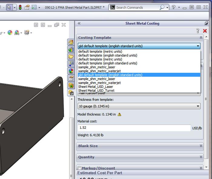
The Costing tool makes it easy for the analyst to select one of several costing templates from a drop-down list. Figure 2 shows the costing templates on my installation.
You’ve probably surmised that the Costing Template sets the prices used for the costing calculation. You might switch between costing templates for punching, laser cutting, or waterjet cutting to get a sense of the relative cost of manufacturing using various processes and production quantities.
If the Costing Template has misleading values, then the resulting costing report will be misleading. One obvious challenge in accurate costing is dealing with fluctuating prices for raw material and labor. Another is to set reasonable rates for setup and machine cycles. The operator’s manual that comes with the Costing tool emphasizes that the user should consult with the manufacturing department when setting up the Costing Template.
If you are operating a contract manufacturing service or a job shop and have a customer base with the Costing tool available, you might consider publishing a Costing Template for the benefit of your customers. If your “customer” is another department in your organization, the Costing tool could help constrain and optimize the designs to a preferred set of materials and manufacturing processes.
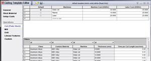
Figure 5a: The cut operations in the Machining Costing Template Editor are shown.
The Costing tool deals with two categories of manufacturing—machining and sheet metal. Sheet Metal Costing, seen in Figure 1, deals with cuts and bends. Machining Costing, shown in Figure 3, deals with milling and drilling. The two categories of costing have much in common regarding how their templates are used and maintained.
When considering the effort of producing costing templates, the CAD operator needs to understand a bit about what the Costing tool needs from the Costing Template. With that in mind, you’ll be able to decide on your goals for the template. As a heads-up, the best accuracy might be achieved by having a suite of Costing Template files that are brief and easy to edit, even if they are numerous. As an alternative to numerous files and to ensure ease of use and publication, the CAD operator might consider having a single template that covers all process and material combinations that you want to be able to compare.
Before making any recommendations in the design of costing templates, we now consider what the Costing tool needs to do as it scans the 3-D model’s features.
For a sheet metal part, the Costing tool translates each modeled feature into one of four manufacturing operations: cut, bend, library, or custom. For a machined part—or a flat plate part—the operations are cut, mill, drill, library, or custom.
Library features include forming tool/stamping operations to create shapes such as louvers, ribs, or standard pockets. Custom operations include plating and painting; these are included in the template for the convenience of the CAD jockey, or the costing analyst in this case, so that person might add the cost for plating from a drop-down list.
Sheet metal part cutting cost is based on one of two methods: stroke cut (punching) or length cut (laser, plasma, or waterjet cutting). Machined part cutting cost is based on time. Cuts include internal holes as well as the perimeter cut length needed to profile the part.
The Sheet Metal Costing Template will provide the data for calculating both the machine setup cost and per-bend cost.
The Costing tool uses a combination of material alloy, material thickness, and bending method in the cost look-up process. Other features—countersinks, tapped holes, and shapes created with forming tools—are handled the same way: Match the feature to the material to the Cut Method and look up the setup and cycle costs.
Note the repeating theme: The manufacturing method is matched to a material in order to look up the cost. If no matching pair of process and material is found in the Costing Template, then the cost is unassigned for that feature.
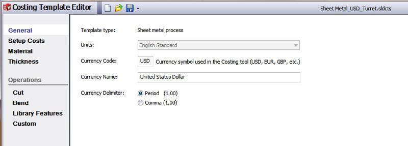
Now let’s get into some detail about the Sheet Metal Costing Template—Figure 4a. The unit of measure and currency format are set using the Costing Template Editor. These can be found under the “general” settings.
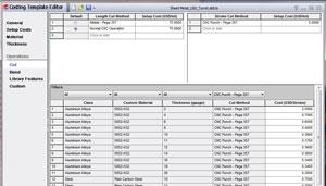
Figure 5b: The cut operations in the Sheet Metal Costing Template Editor are shown.
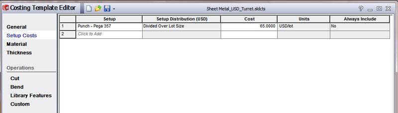
Setup costs—seen in Figure 4b—are per-order settings for expenses that apply no matter how many batches are run to complete the total order quantity. These might include one-time CNC programming or work order preparation. Such global setup costs can be amortized over lot size or per part. Even if you opt to exclude an item in the costing report sometimes, it will still be conveniently available to you for manual override. Note that setup costs that apply to specific machines will be entered elsewhere in the Costing Template.
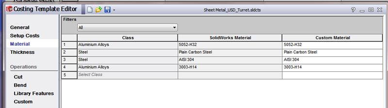
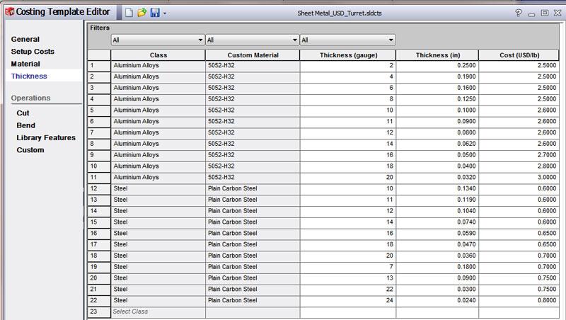
A table can be found in the Costing Template for translating the model’s material into a costing class (see Figure 4c). The class is used to look up costs found elsewhere in the Costing Template. This layer of abstraction—changing modeled material into material class—has at least a couple of benefits for you when designing the Costing Template. First, you can treat several alloys identically for costing purposes. Second, you can add a Custom Material description for each of your new material costing classes.
Consider an example scenario where the designers using this Costing Template might model aluminum parts using either 3003-H14 or 5052-H32. The CAD operator applies these materials to the model to calculate mass and center of gravity. For the purposes of our example Costing Template, the CAD jockey finds no significant difference between the alloys. Thus, the Costing Template needs only one class—which can be called Aluminum Alloys. If the CAD model uses either 3003 or 5052, it will translate into our costing aluminum alloy class for costing purposes.
Another table in the Costing Template translates class and thickness into cost (see Figure 4d). The table has a row for each pair of class and thickness that you want to set a price for. You enter the thickness in both the gauge and decimal values.
If your Costing Template includes most of the standard gauges for aluminum sheet, you’ll have about 11 to deal with—for example, 0.032, 0.040, 0.050, 0.062, 0.080, 0.090, 0.100, 0.125, 0.160, 0.190, and 0.250. Keep in mind that this inventory of thickness costs applies to each material class. If you want to be able to compare costs for various aluminum alloys (for example, 3003-H14, 5052-H32, or 6061-T6), you have to set up three classes and all of the matching thicknesses.
For each pair of class and thickness—33 table entries in this example of three classes with 11 thicknesses each—you’ll need to enter a cost per pound. That is how the system translates material thickness and weight into material cost. To determine how much it costs to process the material, the Operations table is used.
In my experience, price per pound is not constant over time. When designing a Costing Template, consider the maintenance effort. How often do you want to traverse 33 rows in a table to update costs?
If we combine all three alloys into one class, then our example would have only 11 costs to update each time aluminum prices change. In the case of aluminum, it would not be accurate to price 3003 the same as 6061. However, you are the one defining the goals for the Costing Template. The more detail you put into a single template, the more work it takes to use and maintain it. The example templates that ship with the software provide a good starting point.
I have had success combining all aluminum alloys into a single class and setting a very high price per pound for each thickness. I forgive myself for this sin for two reasons: Material typically is not the dominant cost contributor, and the goal of my template is to give a reasonable cost comparison, not a guaranteed price quotation.
I create a separate costing class, Steel, and toss ferrous alloys into it (see Figure 4c). I then create the required thickness entries for that class. This allows my users to compare a material switch from steel to aluminum in general terms, not necessarily an accurate comparison between 3003-H14 aluminum and 304 2B stainless. When deciding what materials to include in your class, try to anticipate which materials the CAD jockey is likely to select. If your table doesn’t include the material and thickness they’ve chosen, the Costing Template won’t be as automatically useful.
You’ll also use the Costing Template Editor to set up the four manufacturing categories of manufacturing operations—cut, bend, library, or custom in a sheet metal template or cut, mill, drill, library, or custom in a machining template.
Both kinds of templates have an Operations category. Let’s consider the settings for the cut operation first. In both kinds of templates, you enter the machine data and then enter the processing cost for each material.
In a Machining Costing Template (see Figure 5a), the cut tab displays two tables. The upper table lists the machines capable of parting raw blanks for a machined part. Band saw, laser, plasma, and waterjet are common examples of what you might enter here. At least one machine must be listed in this table. If more than one is listed, then select the default machine to use for cut. You can use the other entries to compare manufacturing method costs. Separate entries are available for the cost per hour for the machine and for the labor.
In a Sheet Metal Costing Template (see Figure 5b), two sections in the upper machine table can be found, one for Length Cut Method and another section for Stroke Cut Method. Each section can list one or more machines with one as the default. You need at least one machine for the cut operations. Unlike the machined part template that is calculating hourly costs, sheet metal template cutting machines have a single Setup Cost that will be amortized over the batch quantity.
Once you have a machine, you can set up a cycle cost. The cycle cost section has a row for each combination of class (material), thickness (gauge), and method. For machined part cutting—shown in Figure 5a—you’ll enter the amount of time. For sheet metal cutting—shown in Figure 5b—you enter the amount of money. This will be either dollar per stroke or dollar per length, depending on the cutting method.
To calculate how many cycle cost rows could be needed, multiply the number of manufacturing methods by the number of entries in the Thickness table. In our example, we had 33 class thicknesses. If we cut and bend, then we’ll have 66 operation costs to enter into the table.
You do not necessarily have to enter all possible combinations of material and method. For example, your laser may cut only a limited range of thicknesses. Or you might never bend 7075-T6 aluminum. You do need to enter all of the combinations that your CAD jockey is likely to model, however.
The process for setting up prices for bends, milled features, library features, and drilled features is similar to that for cuts.
The costs set for the various manufacturing processes are yours to determine. My basic recommendation is to use prices that represent the significant differences between manufacturing processes. Lasers are quick to set up, but cost more per inch of cut than turret presses. If your Costing Template is properly set up, it will convey wisdom such as that to your designers.
Gerald would love to have you send him your comments and questions. You are not alone, and the problems you face often are shared by others. Share the grief, and perhaps we will all share in the joy of finding answers. Please send your questions and comments to dand@thefabricator.com.


The Fabricator is North America's leading magazine for the metal forming and fabricating industry. The magazine delivers the news, technical articles, and case histories that enable fabricators to do their jobs more efficiently. The Fabricator has served the industry since 1970.
start your free subscription
Easily access valuable industry resources now with full access to the digital edition of The Fabricator.

Easily access valuable industry resources now with full access to the digital edition of The Welder.

Easily access valuable industry resources now with full access to the digital edition of The Tube and Pipe Journal.

Easily access valuable industry resources now with full access to the digital edition of The Fabricator en Español.
In this episode of The Fabricator Podcast, Caleb Chamberlain, co-founder and CEO of OSH Cut, discusses his company’s...


